Image pickup apparatus
a technology of image pickup and image, which is applied in the field of image pickup apparatus, can solve the problems of affecting the effect of extending the range of subject illumination, affecting the image quality of the picked-up image, and affecting the image quality of the image, so as to achieve the effect of high image quality
- Summary
- Abstract
- Description
- Claims
- Application Information
AI Technical Summary
Benefits of technology
Problems solved by technology
Method used
Image
Examples
first embodiment
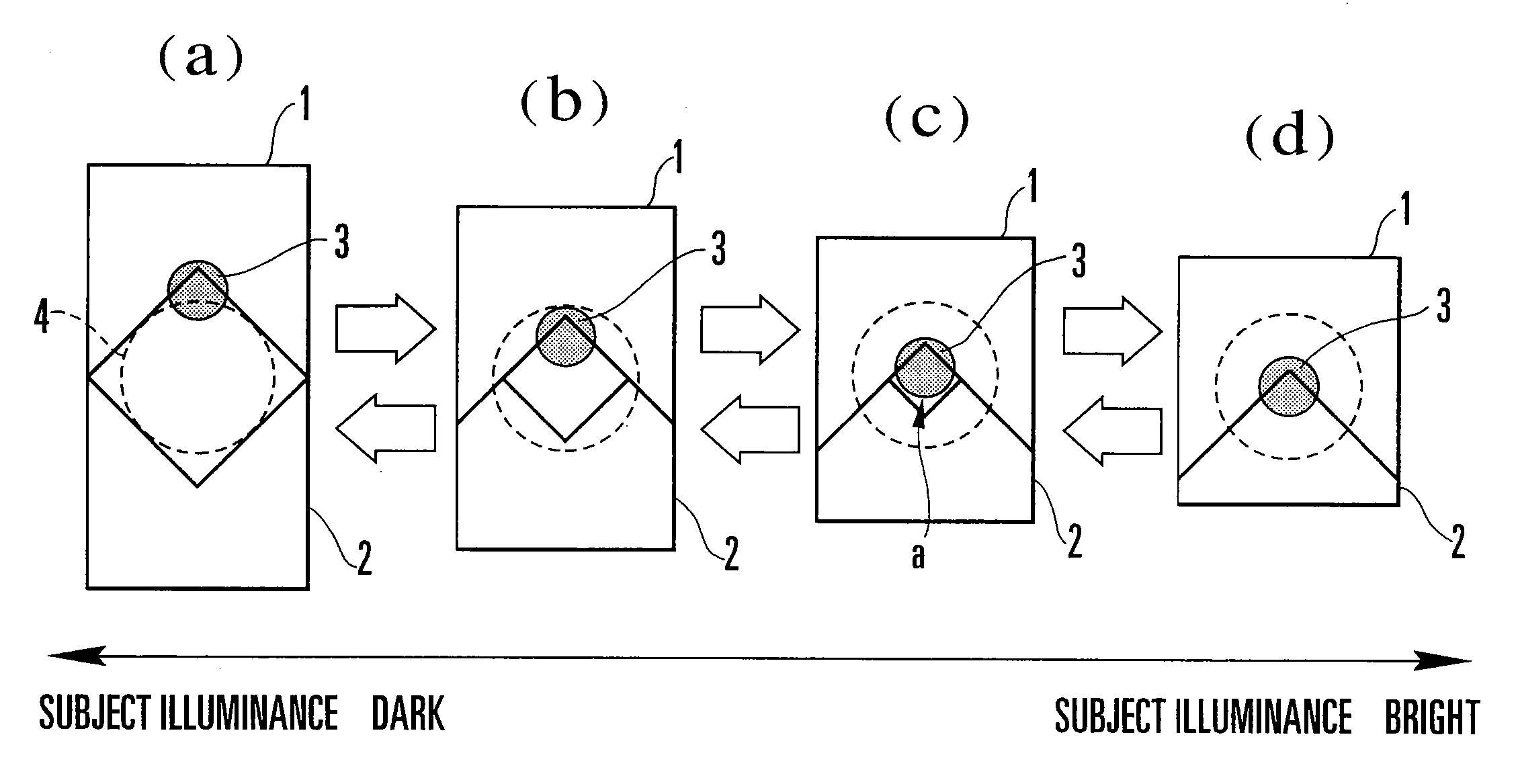
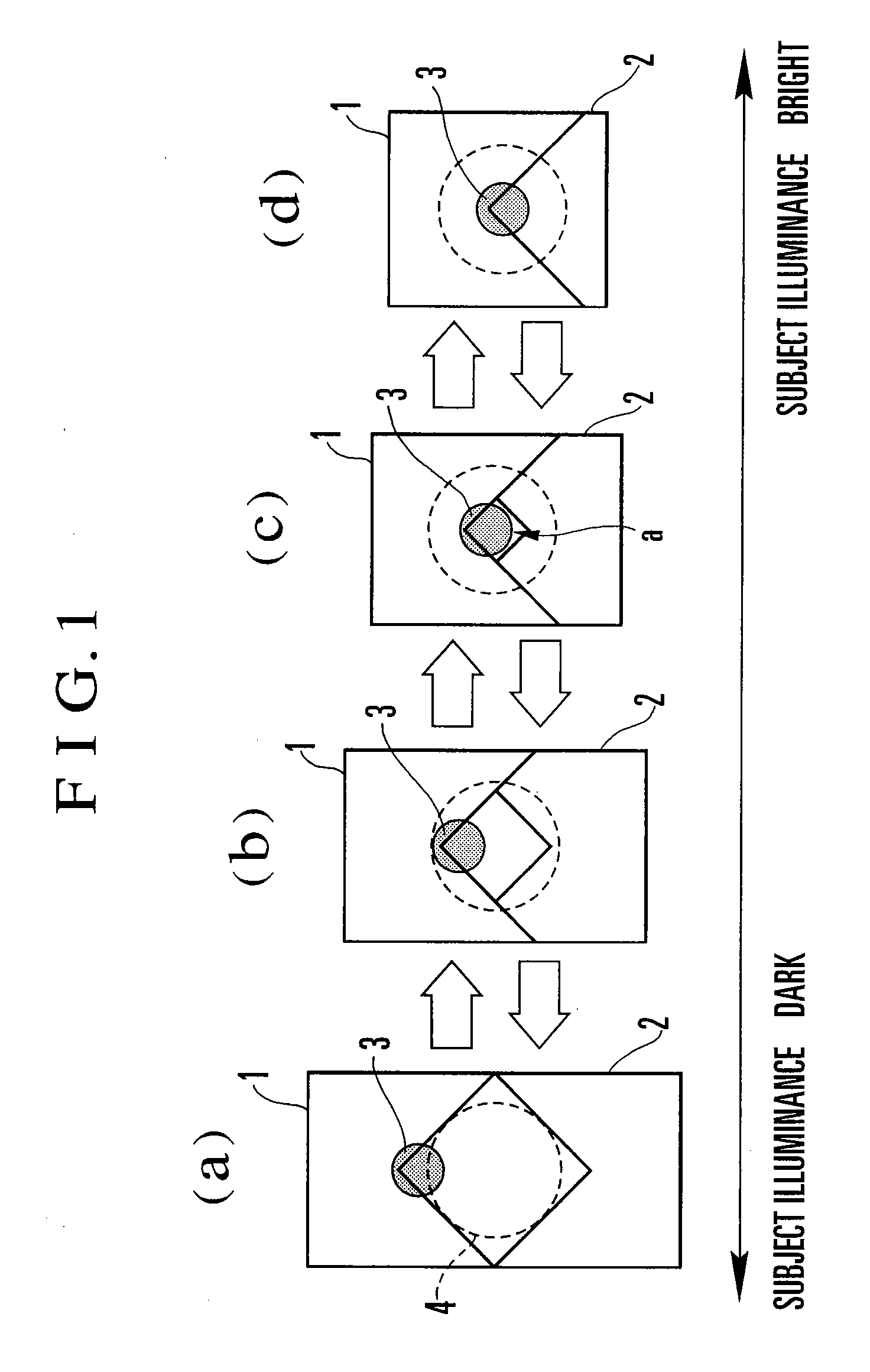
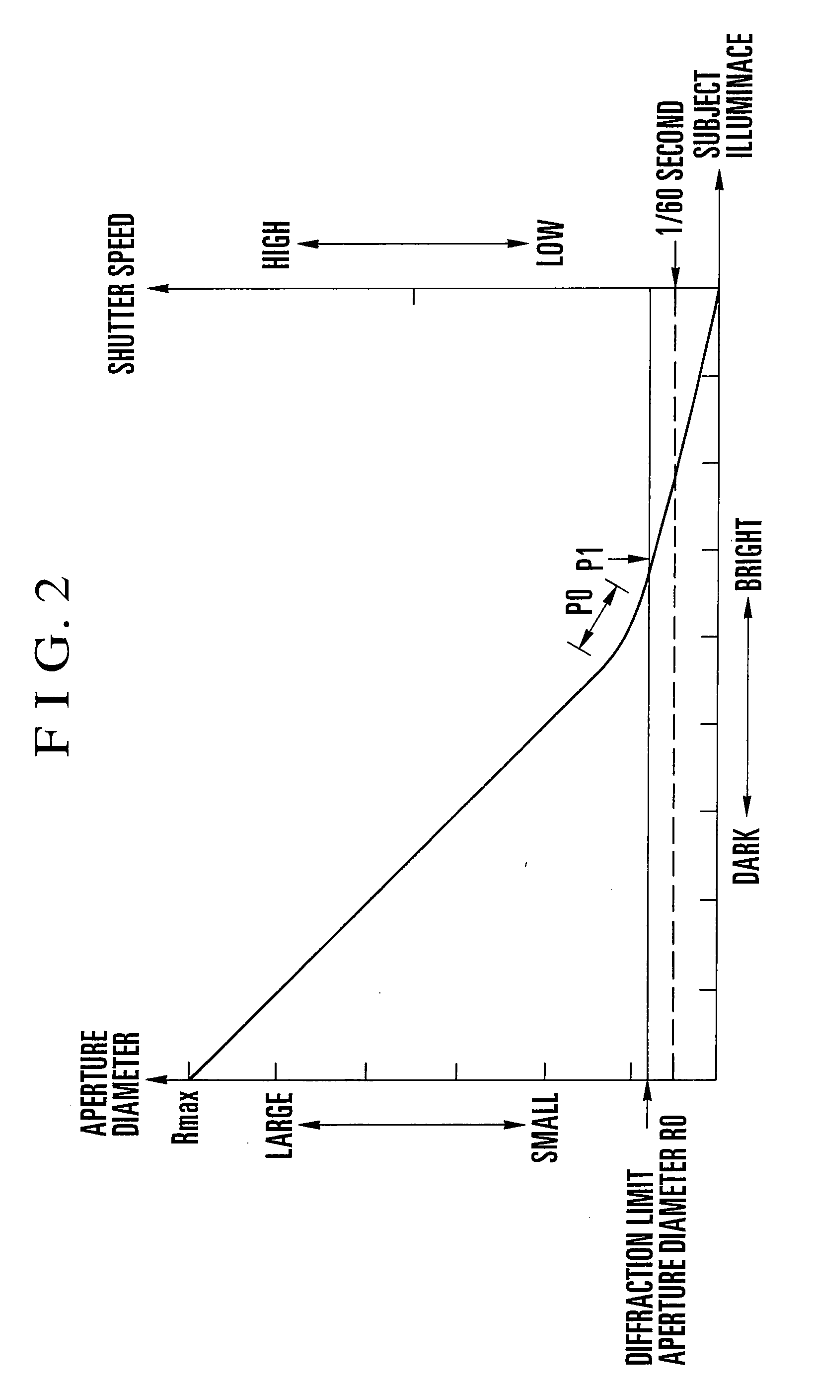
[0057]FIG. 3 shows an image pickup apparatus according to a first embodiment of the present invention. In the image pickup apparatus, lenses 101 and 102 constitute a photographing optical system having an optical axis 100, and an ND filter (neutral-density filter) 104 and a diaphragm device 106 are disposed along the optical axis 100. The ND filter 104 is arranged to be inserted into or retracted from an optical path in which the ND filter 104 completely covers the aperture of the diaphragm device 106, by an ND filter driving part 103, and the diaphragm device 106 is controlled by a diaphragm driving part 105. The ND filter 104 and the diaphragm device 106 are controlled independently of each other.
[0058] A subject image which has passed through this photographing optical system is focused on an image pickup element 107. The signal outputted from the image pickup element 107 is converted into a standard television signal by a video signal processing circuit 108, and the video signa...
second embodiment
[0075]FIG. 7 shows a flowchart of the operation of an image pickup apparatus (a light quantity control part) according to a second embodiment of the present invention. The basic construction of the image pickup apparatus according to the second embodiment is approximately identical to that of the image pickup apparatus according to the first embodiment of the present invention, and in FIG. 7, common constituent elements are denoted by reference numerals identical to those used in the first embodiment.
[0076] The second embodiment differs from the first embodiment in that the shutter speed (storage time) of the image pickup element 107 is increased or decreased at the same that the ND filter 104 is inserted or retracted. In addition, in the second embodiment, the light quantity control part 110 reads a shutter speed from the program diagram shown in FIG. 8 in accordance with a luminance signal of a subject image or an aperture value signal, and outputs a shutter speed control signal ...
third embodiment
[0139]FIG. 12 is a view showing two light quantity adjusting means which is suitable for carrying out the third embodiment of the present invention.
[0140] Referring to FIG. 12, a diagram device 401 includes constituent components 403 to 407. The constituent component 403 is a diaphragm driving meter, the constituent component 404 is an output shaft of the diaphragm driving meter 403, and the constituent component 405 is an interlocking portion which interlocks the diaphragm driving meter 403 and a windmill component which turns about an optical axis in interlocking relation to the rotation of the output shaft 404. This windmill component has blades and an interlocking pin (none of which is shown) and is arranged to move the blades by the turning of a windmill.
[0141] The constituent components 406 are blades. The example shown in FIG. 6 uses six blades so that a hexagonal aperture can be formed, but the number of blades is not limited to six.
[0142] As is well known, a diaphragm de...
PUM
 Abstract
Description
Claims
Application Information
 - R&D
- Intellectual Property
- Life Sciences
- Materials
- Tech Scout
- Unparalleled Data Quality
- Higher Quality Content
- 60% Fewer Hallucinations
Browse by: Latest US Patents, China's latest patents, Technical Efficacy Thesaurus, Application Domain, Technology Topic, Popular Technical Reports.
© 2025 PatSnap. All rights reserved.Legal|Privacy policy|Modern Slavery Act Transparency Statement|Sitemap|About US| Contact US: help@patsnap.com


