Methods and apparatus for double flow turbine first stage cooling

a technology of double flow turbine and first stage cooling, which is applied in the direction of mechanical equipment, machines/engines, liquid fuel engines, etc., can solve the problems of insufficient driving force to provide sufficient cooling steam flow, and may not achieve steady stage temperatur

Inactive Publication Date: 2007-03-22
GENERAL ELECTRIC CO
View PDF11 Cites 24 Cited by
  • Summary
  • Abstract
  • Description
  • Claims
  • Application Information

AI Technical Summary

Benefits of technology

[0004] In one aspect, a method for cooling a double flow steam turbine is provided. The method includes supplying steam to the turbine to form a main inlet steam flow, allowing steam to bleed from the main inlet flow to an annulus bounded by an inner shell, nozzle plate and rotor body of the turbine, and directing the bleed steam to bucket dovetail steam balance holes.
[0005] In another aspect, a cooling steam flow path through a double flow steam turbine is provided. The steam flow path includes an annulus bounded by an inner shell, nozzle plate, and rotor body of a turbine. The flow path extends from the annulus to a bucket wheel space, and from the bucket wheel space into bucket dovetail steam balance holes. The flow path extends from the bucket dovetail steam balance holes to a stage exit main flow.

Problems solved by technology

For example, there may be insufficient driving force to provide sufficient cooling steam flow in all areas of the turbine.
As a result, a steady stage temperature may not be achieved.

Method used


Image

  • Methods and apparatus for double flow turbine first stage cooling
  • Methods and apparatus for double flow turbine first stage cooling

Examples


Embodiment Construction

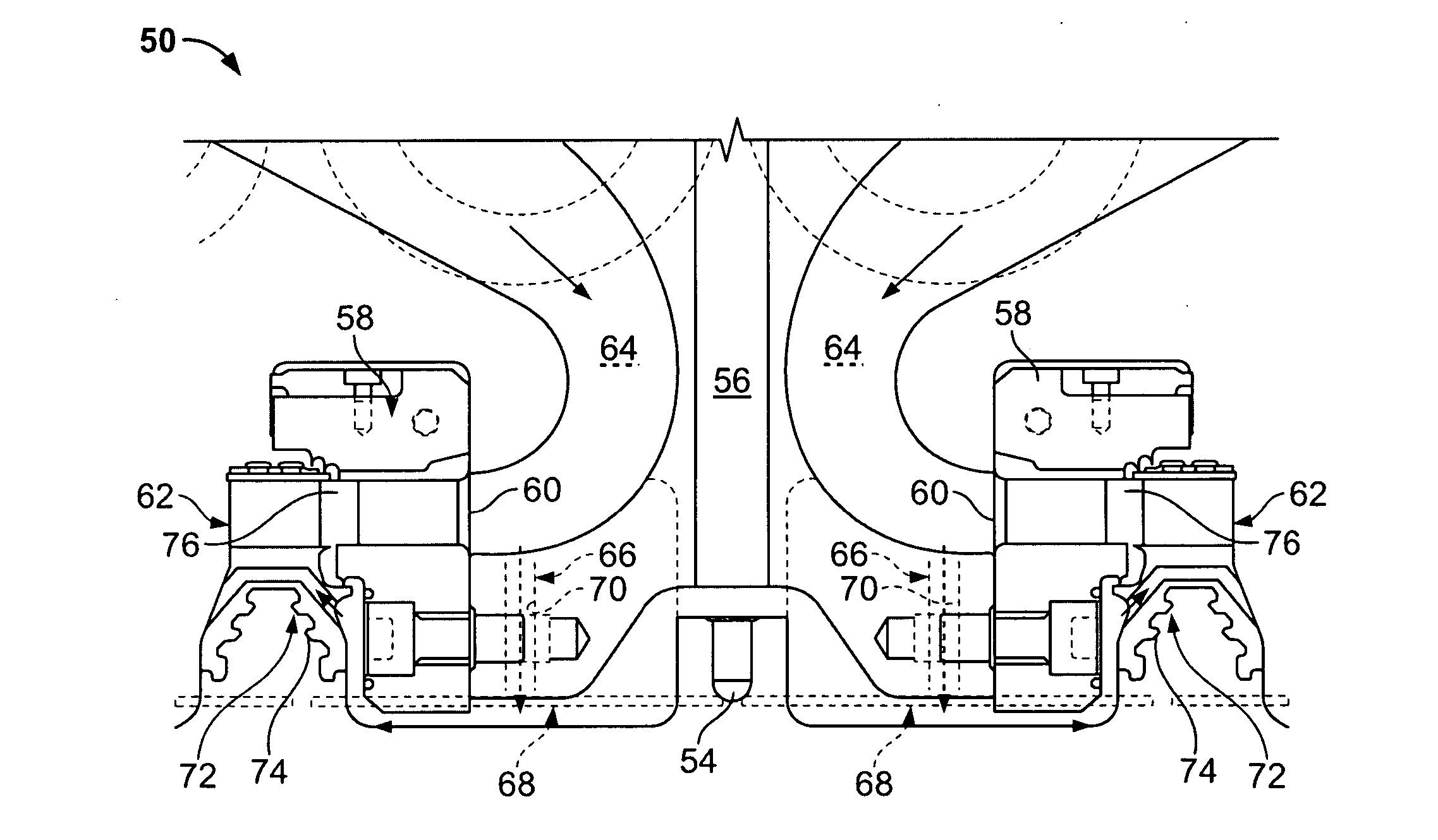
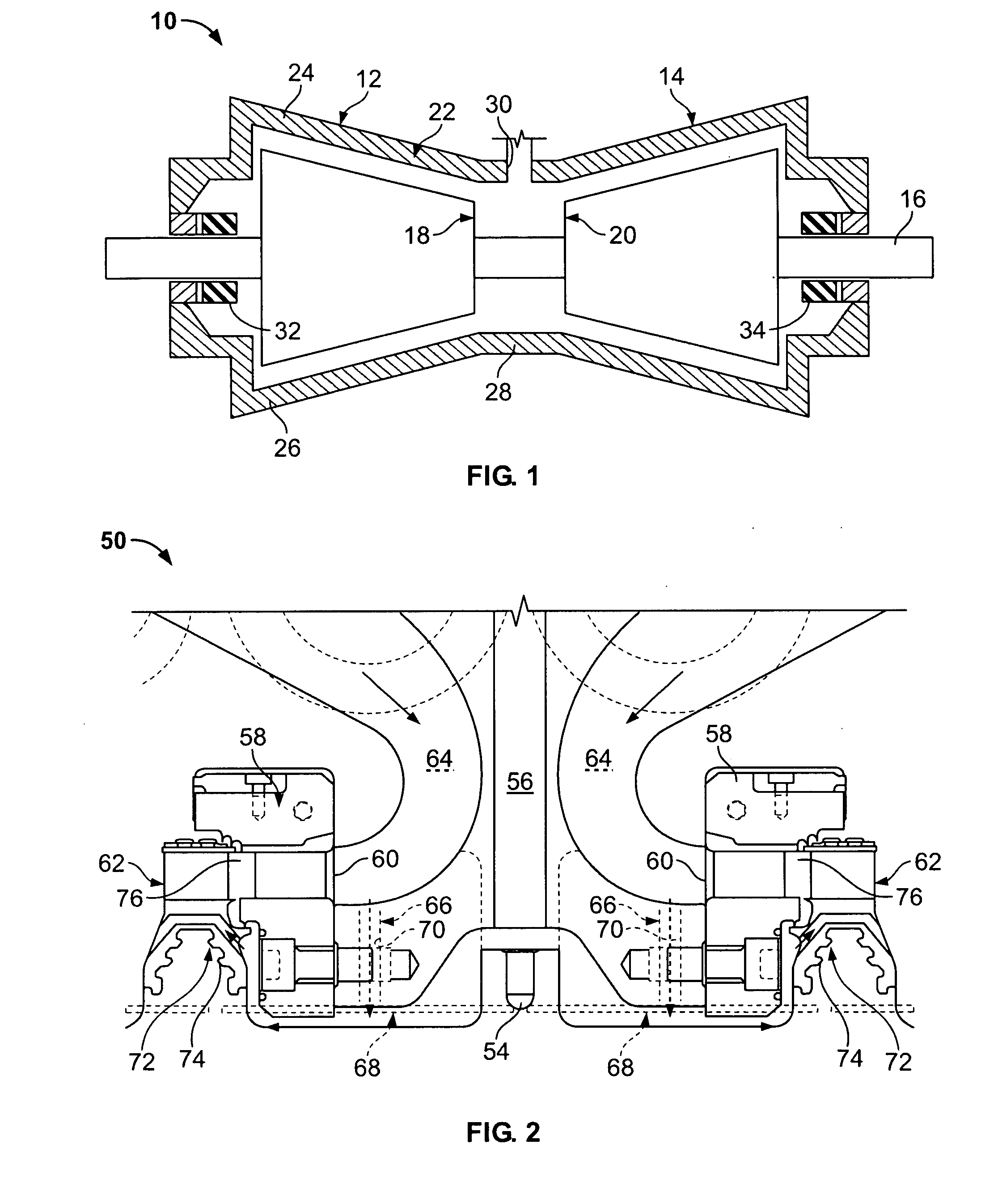
[0009]FIG. 1 is a schematic illustration of an example opposed-flow steam turbine 10. Turbine 10 includes first and second high pressure (HP) sections 12 and 14. A rotor shaft 16 extends through sections 12 and 14. Each HP section 12 and 14 includes a nozzle 18 and 20. A single outer shell or casing 22 is divided axially into upper and lower half sections 24 and 26, respectively, and spans both HP sections 12 and 14. A central section 28 of shell 22 includes a high pressure steam inlet 30. Within outer shell or casing 22, HP sections 12 and 14 are arranged in a single bearing span supported by journal bearings 32 and 34.

[0010] In operation, high pressure steam inlet 30 receives high pressure / high temperature steam from a source, for example, a power boiler (not shown). The steam is routed through HP sections 12 and 14 wherein work is extracted from the steam to rotate rotor shaft 16. The steam exits HP sections 12 and 14 and is routed, for example, to an intermediate pressure turbi...


PUM


Abstract

Method and apparatus for cooling a double flow steam turbine are provided. In one embodiment, the method includes supplying steam to the turbine to form a main inlet steam flow, allowing steam to bleed from the main inlet flow to an annulus bounded by an inner shell, nozzle plate and rotor body of the turbine, and directing the bleed steam to bucket dovetail steam balance holes.

Description

BACKGROUND OF THE INVENTION [0001] This invention relates generally to steam turbines, and more particularly, to cooling a first stage of a double flow turbine. [0002] A steam turbine typically includes a high-pressure (HP) turbine section, an intermediate-pressure (IP) turbine section, and a low-pressure (LP) turbine section. Each turbine section includes rotatable steam-turbine blades fixedly attached to, and radially extending from, a steam-turbine shaft. The shaft is rotatably supported by bearings. The bearings may be located longitudinally outwardly from the turbine sections. [0003] A steam turbine has a defined steam path which includes, in serial-flow relationship, a steam inlet, a turbine, and a steam outlet. Some areas in a steam turbine may become stagnant with respect to steam flow. For example, there may be insufficient driving force to provide sufficient cooling steam flow in all areas of the turbine. As a result, a steady stage temperature may not be achieved. That is...

Claims


Application Information

Patent Timeline
Patent Type & Authority Applications(United States)
IPC IPC(8): F03B11/00
CPCF01D5/081F01D5/082F01D25/08F01D25/12F05D2240/81F05D2220/31F05D2260/2322F05D2260/205F02C7/16
Inventor CORNELL, DANIEL RICHARD
Owner GENERAL ELECTRIC CO
Why Eureka
Try Eureka