Torsion beam suspension member

a technology of twisting beam and suspension member, which is applied in the direction of axle unit, wheels, transportation and packaging, etc., can solve the problems of increasing production costs of a complete twisting beam axle, complex manufacturing of these transverse struts,

Inactive Publication Date: 2007-03-29
DANA AUTOMOTIVE SYST GRP LLC
View PDF27 Cites 81 Cited by
  • Summary
  • Abstract
  • Description
  • Claims
  • Application Information

AI Technical Summary

Problems solved by technology

Manufacture of these transverse struts is, however, very complex so that production costs of a complete twist-beam axle are increased.

Method used


Image

  • Torsion beam suspension member
  • Torsion beam suspension member
  • Torsion beam suspension member

Examples


Embodiment Construction

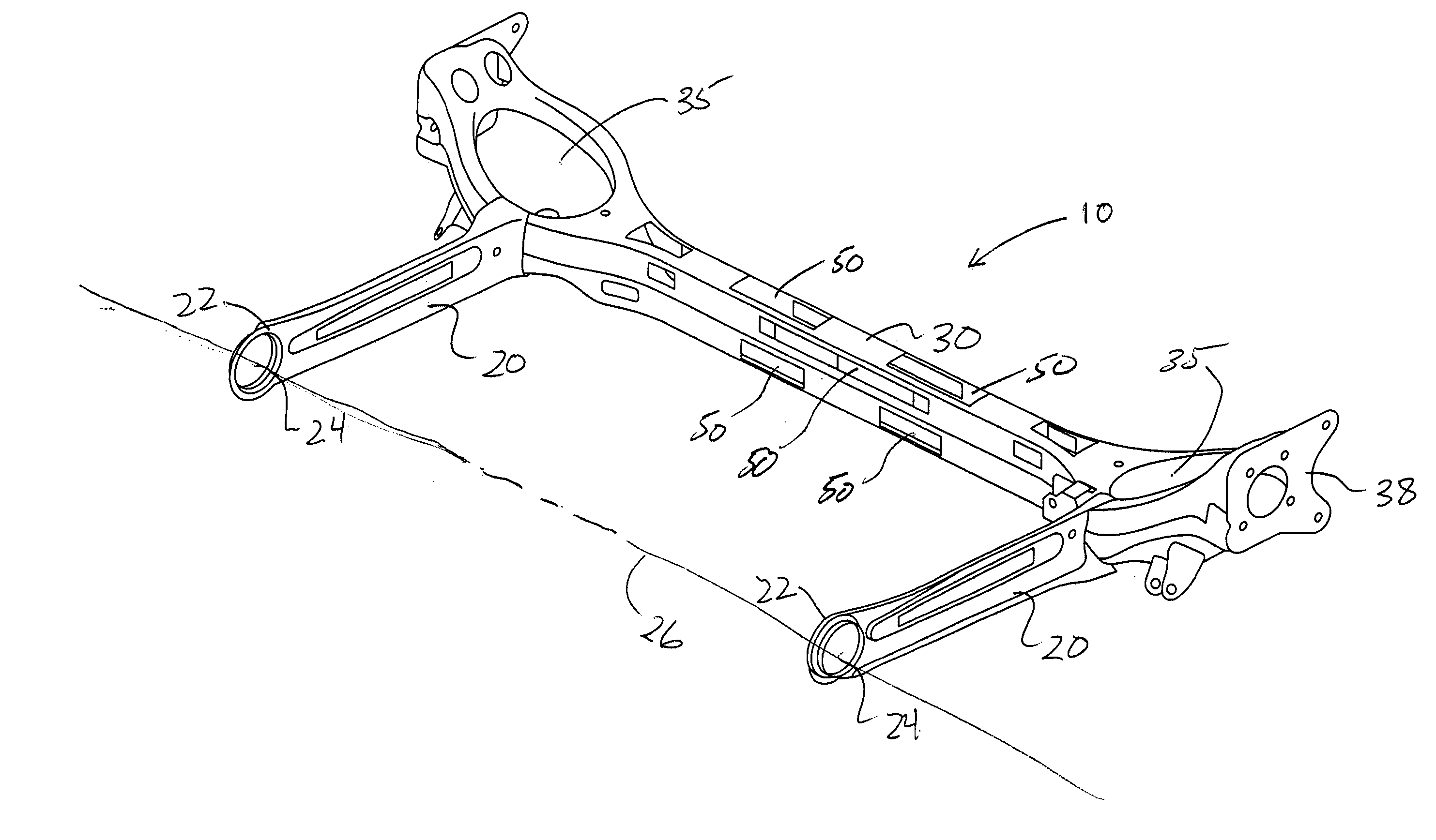
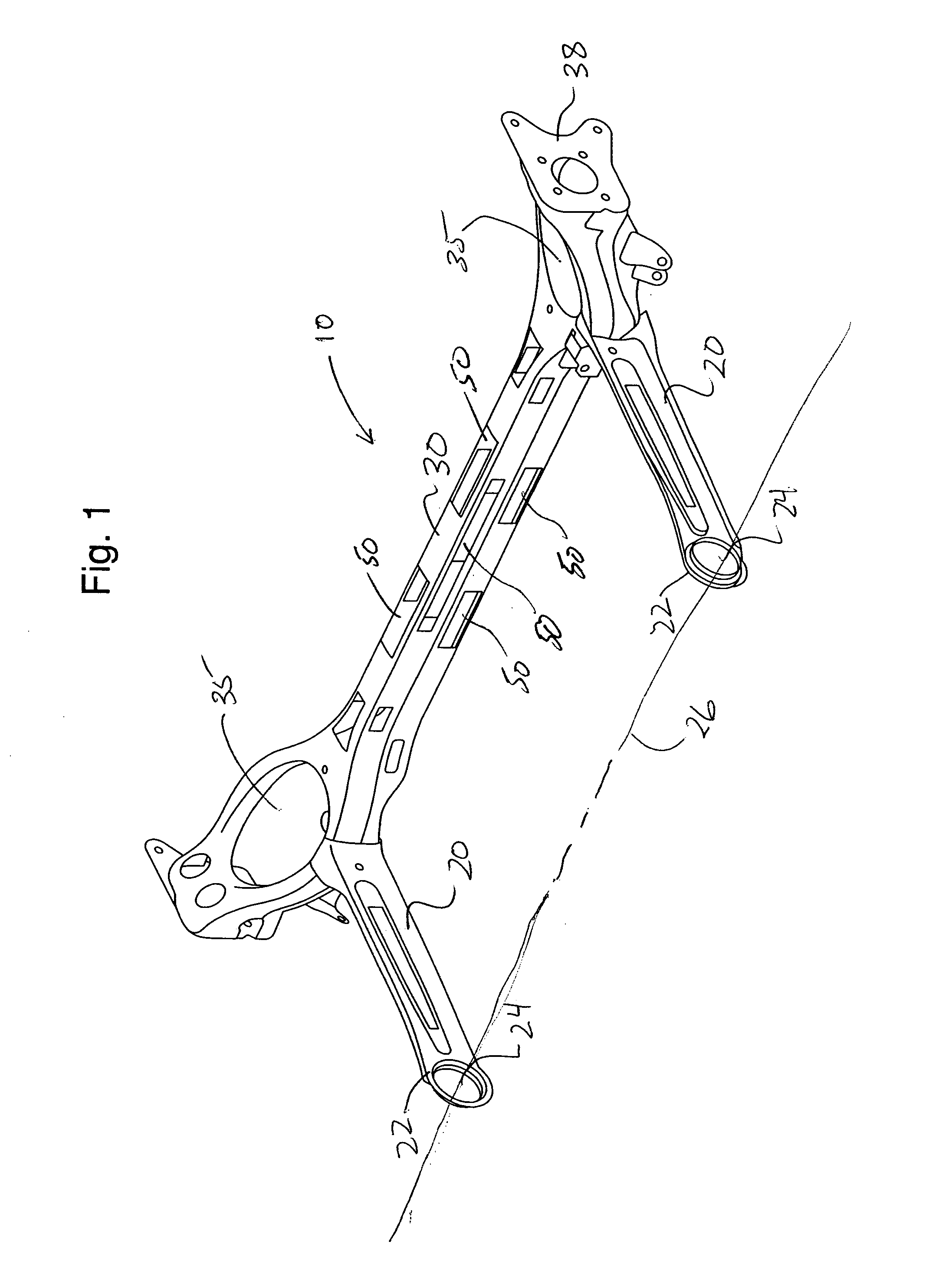
[0027]FIG. 1 shows one preferred embodiment of the present invention whereby the twist axle assembly 10 is adapted to be mounted to the underside of a vehicle body (not shown) at a pair of pivot points defined by bushings (not shown). The bushings are typically disposed at a forward or leading end 22 of the control arms 20 in circular bushing apertures 24. The control arms 20 typically extend rearward from the bushing apertures 24. The control arms 20 extend generally parallel to the longitudinal axis of the vehicle and are generally parallel spaced from one another. The bushings define an axle assembly pivot axis 26 about which the axle assembly pivots after being mounted in the vehicle body.

[0028] The transverse twist beam axle 30 connects the control arms 20. The twist beam axle 30 extends generally parallel to pivot axis 26 and transverse to the longitudinal axis of the vehicle. A spring seat 35 is provided adjacent the intersection area of the twist beam 30 and the control arm...


PUM

PropertyMeasurementUnit
massaaaaaaaaaa
massaaaaaaaaaa
massaaaaaaaaaa

Abstract

A torsion beam suspension member using two u-shaped, stamped members that are superimposed and welded to form a torsion arm. No additional torsion tube or bar is needed. Tuning holes (rectangular, oblong, round or any other suitable shape) are used to change or tune the torsional resilience of the suspension. In the preferred embodiment, the tuning holes are oblong and located near the center of the cross member. The tuning holes are selected based on having target value for torsional compliance or resilience. The size, quantity and location of the tuning hole are chosen based on computer analysis. An optimization or iterative process is used to arrive at the final hole size, quantity and location.

Description

BACKGROUND OF THE INVENTION [0001] 1. Field of the Invention [0002] The present invention generally relates to suspensions used for a vehicle and the like and, more particularly, to a twist beam type suspension having a twist beam provided between left and right trailing arms. [0003] 2. Description of the Related Art [0004] A twist beam type suspension is known which has a twist beam bridging between left and right control arms. The left and right trailing arms are pivotally supported on a vehicle body at their front ends. The twisted beam is formed substantially in a straight shape and connected at opposite ends to the respective left and right control arms. The twist beam is resistant to bending but resilient relative to torsional stress. [0005] The control arms along their rearward ends typically have connected thereto a spring seat. The spring seat is provided on the control arm to support a suspension coil spring which is disposed between the vehicle body and the control arm. A...

Claims


Application Information

Patent Timeline
Patent Type & Authority Applications(United States)
IPC IPC(8): B60G11/20B60B35/00B21D53/88
CPCB21D53/88B60B35/04B60B35/08B60G11/64B60G21/051B60G2204/124Y10T29/49622B60G2204/126B60G2206/20B60G2206/427B60G2206/722B60G2206/8103B60G2206/8201B60G2204/1246
Inventor RINEHART, RONALD A.KROPPE, WILLIAM J.LIBROCK, SCOTT
Owner DANA AUTOMOTIVE SYST GRP LLC
Why Eureka
Try Eureka