Radio apparatus

a radio and apparatus technology, applied in the field of radio apparatus, can solve problems such as increasing the error ra

Inactive Publication Date: 2007-03-29
KK TOSHIBA
View PDF7 Cites 23 Cited by
  • Summary
  • Abstract
  • Description
  • Claims
  • Application Information

AI Technical Summary

Benefits of technology

[0018]FIG. 6 is a view showing a transmission period of

Problems solved by technology

However, since the characteristics of the respective oscillators vary, the characteristics of the s

Method used


Image

  • Radio apparatus
  • Radio apparatus
  • Radio apparatus

Examples


first embodiment

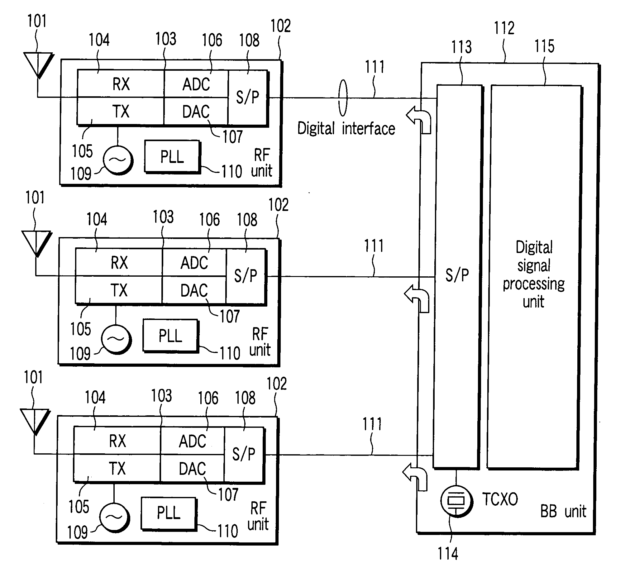
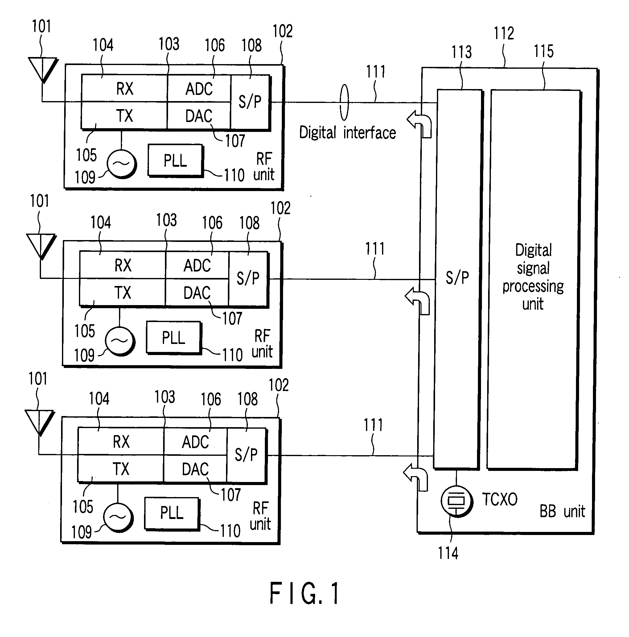
[0025] A radio apparatus according to the first embodiment of the present invention will be described with reference to FIG. 1. FIG. 1 is a block diagram when a baseband processing unit has a reference signal source, and a reference signal from the reference signal source is distributed to radio units via digital interfaces.

[0026] A plurality of antennas 101, RF units 102, and digital interfaces 111, and a baseband processing unit 112 are provided. Each RF unit 102 includes a radio unit 103, synthesizer (VCO: Voltage-Controlled Oscillator) 109, and PLL circuit 110. The radio unit 103 serves as an RF-IC, and incorporates a receiver (RX) 104, a transmitter (TX) 105, a reception ADC 106, a transmission DAC 107, and a serial-to-parallel converter (S / P) 108. The baseband processing unit 112 serves as a baseband IC, and incorporates a serial-to-parallel converter 113, a temperature compensation quartz oscillator (TCXO) 114 serving as the reference signal source, and a digital signal proc...

second embodiment

Modification of Second Embodiment

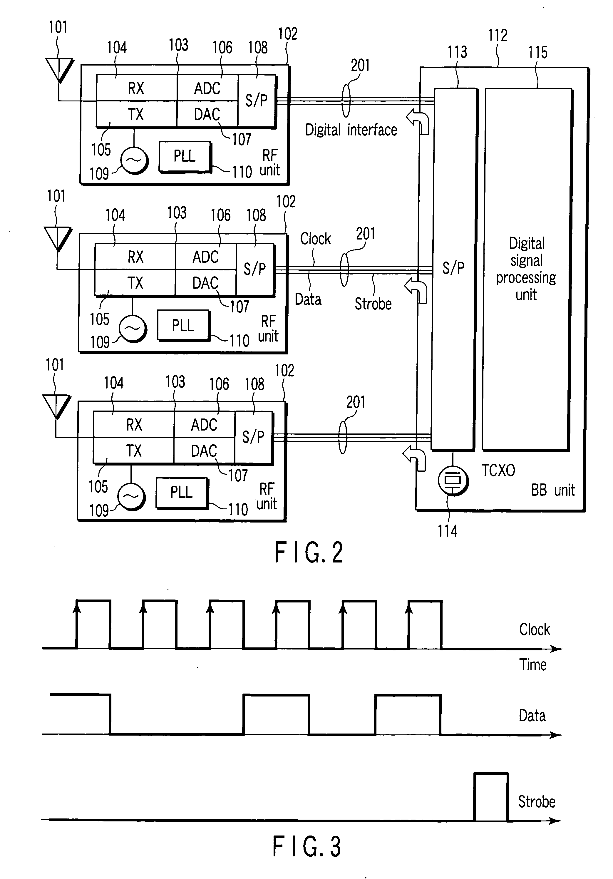
[0039] A modification of the second embodiment will be described with reference to FIG. 4. Similar to FIG. 2, FIG. 4 is a block diagram when the signal from the TCXO is used as the reference clock of the digital interface, and the reference signal is clock-extracted from the transmitted serial bus signal on a radio unit side as the reference of a synthesizer.

[0040] In this modification, each radio unit 103 additionally includes a clock extraction unit 402. Each RF unit 102 is connected to a baseband processing unit 112 via a digital interface 401 using one signal line.

[0041] Only a DATA signal is transmitted via the digital interface 401 serving as one serial signal line.

[0042] The clock extraction unit 402 receives the DATA signal, and clock extraction is done from this DATA signal. Since the clock-extracted signal is the same as the reference signal of the TCXO 114, this signal can be used as the reference signal for the synthesizers. As a resul...

third embodiment

Modification of Third Embodiment

[0057] In this modification, control signals are collected and exchanged via a physically different signal line. A radio apparatus according to this modification will be described with reference to FIG. 7.

[0058] In this modification, each RF unit 102 includes two serial-to-parallel converters 703 and 704 which are connected to a serial-to-parallel converter 113 via respective digital interfaces 701 and 702. Transmission and reception data are transmitted between the serial-to-parallel converter 703 and the serial-to-parallel converter 113 via the digital interface 701, and control data is transmitted between the serial-to-parallel converter 704 and the serial-to-parallel converter 113 via the digital interface 702. Note that the example in the third embodiment may be combined with the modification of the third embodiment.

[0059] More specifically, in the radio apparatus such as MIMO having the plurality of RF units, since the RF units 102 are control...


PUM


Abstract

A radio apparatus includes a first radio-frequency unit configured to receive a reception signal transmitted from a communication partner, and configured to transmit a transmission signal to the communication partner, a second radio-frequency unit configured to receive a reception signal transmitted from the communication partner, configured to transmit a transmission signal to the communication partner, a baseband processing unit configured to be supplied with the reception signal from each of the first and second radio-frequency units, and supply, to each of the first and second radio-frequency units, data to be transmitted to the communication partner, and the baseband processing unit configured to generate a reference signal supplied to each of the first radio-frequency unit and the second radio-frequency unit, and a digital signal supplying unit configured to supply a digital signal containing the reference signal from the baseband processing unit to each of the first and second units.

Description

CROSS-REFERENCE TO RELATED APPLICATIONS [0001] This application is based upon and claims the benefit of priority from prior Japanese Patent Application No. 2005-283631, filed Sep. 29, 2005, the entire contents of which are incorporated herein by reference. BACKGROUND OF THE INVENTION [0002] 1. Field of the Invention [0003] The present invention relates to a radio apparatus having a digital interface and, more particularly, to a radio apparatus having a plurality of radio units. [0004] 2. Description of the Related Art [0005] Conventionally, in a radio apparatus including an RF (Radio Frequency) unit (radio unit) and a baseband processing unit, an interface includes an analog signal line and a digital and / or analog control line. However, recently, along with the spread of CMOS (Complementary Metal-Oxide Semiconductor) RF-ICs (Integrated Circuit), an ADC (Analog / Digital Converter) or DAC (Digital / Analog Converter) can be incorporated in the RF-IC. Under-this situation, so-called DigRF...

Claims


Application Information

Patent Timeline
IPC IPC(8): H04L5/16H04B1/40H04B7/04H04J99/00
CPCH04L7/0079H04W52/245H04B1/0028H04B1/40H04J3/0685H04W52/42
Inventor YOSHIDA, HIROSHITANABE, YASUHIKOOKUNI, HIDENORISHOKI, HIROKI
Owner KK TOSHIBA
Why Eureka
Try Eureka