Method and arrangement for detecting load mismatch, and a radio device utilizing the same

a radio device and load mismatch technology, applied in the field of radio frequency power amplifiers and their, can solve the problems of antenna mismatch, impedance mismatch between the antenna and the power amplifier, and the practicable antenna is not operating under steady-state conditions, so as to reduce losses and accurately and reliably detect the mismatch of the antenna

Active Publication Date: 2005-11-15
III HLDG 3
View PDF5 Cites 131 Cited by
  • Summary
  • Abstract
  • Description
  • Claims
  • Application Information

AI Technical Summary

Benefits of technology

[0010]It is an objective of the present invention to provide a method and an apparatus for antenna mismatch detection that would allow integration with other components. An additional objective of the invention is to provide a method and an ap

Problems solved by technology

One of the principal issues affecting transmission efficiency is impedance matching between the power amplifier and the antenna.
Problems arise because a practical antenna is not operating under steady-state conditions.
Large and/or well-conducting bodies brought close to the antenna change the impedance characteristics of the antenna, which causes impedance mismatch between the antenna and the power amplifier, commonly referred to as antenna mismatch.
The hand of a user is frequently close enough to the antenna of a portable telephone to cause problems of this kind.
This again tends to give rise to mismatch problems.
Increased transmission loss is not the only negative consequence of impedance mismatch between a power amplifier and an antenna.
Mismatch causes the power amplifier to operate at a needlessly high power level, which tends to cause distortion in the radio frequency signal.
The problem is worst with linear amplifiers, the use of which is mandatory with most amplitude-affecting modulation methods, because the amplification level of a linear amplifier cannot be cut back controllably as a response to a detected antenna mismatch as with nonlinear amplifiers.
It should be noted, though, that linearity problems caused by antenna mismatch are most prominent at high transmission power levels, and consequently their severity in low-power handheld devices is quite modest.
In principle the same problems arise in every transmission application, regardless of whether the power amplifier i

Method used


Image

  • Method and arrangement for detecting load mismatch, and a radio device utilizing the same
  • Method and arrangement for detecting load mismatch, and a radio device utilizing the same
  • Method and arrangement for detecting load mismatch, and a radio device utilizing the same

Examples


Embodiment Construction

[0046]The exemplary embodiments of the invention presented in this patent application are not to be interpreted to pose limitations to the applicability of the appended claims. The verb “to comprise” is used in this patent application as an open limitation that does not exclude the existence of also unrecited features. The features recited in depending claims are mutually freely combinable unless otherwise explicitly stated.

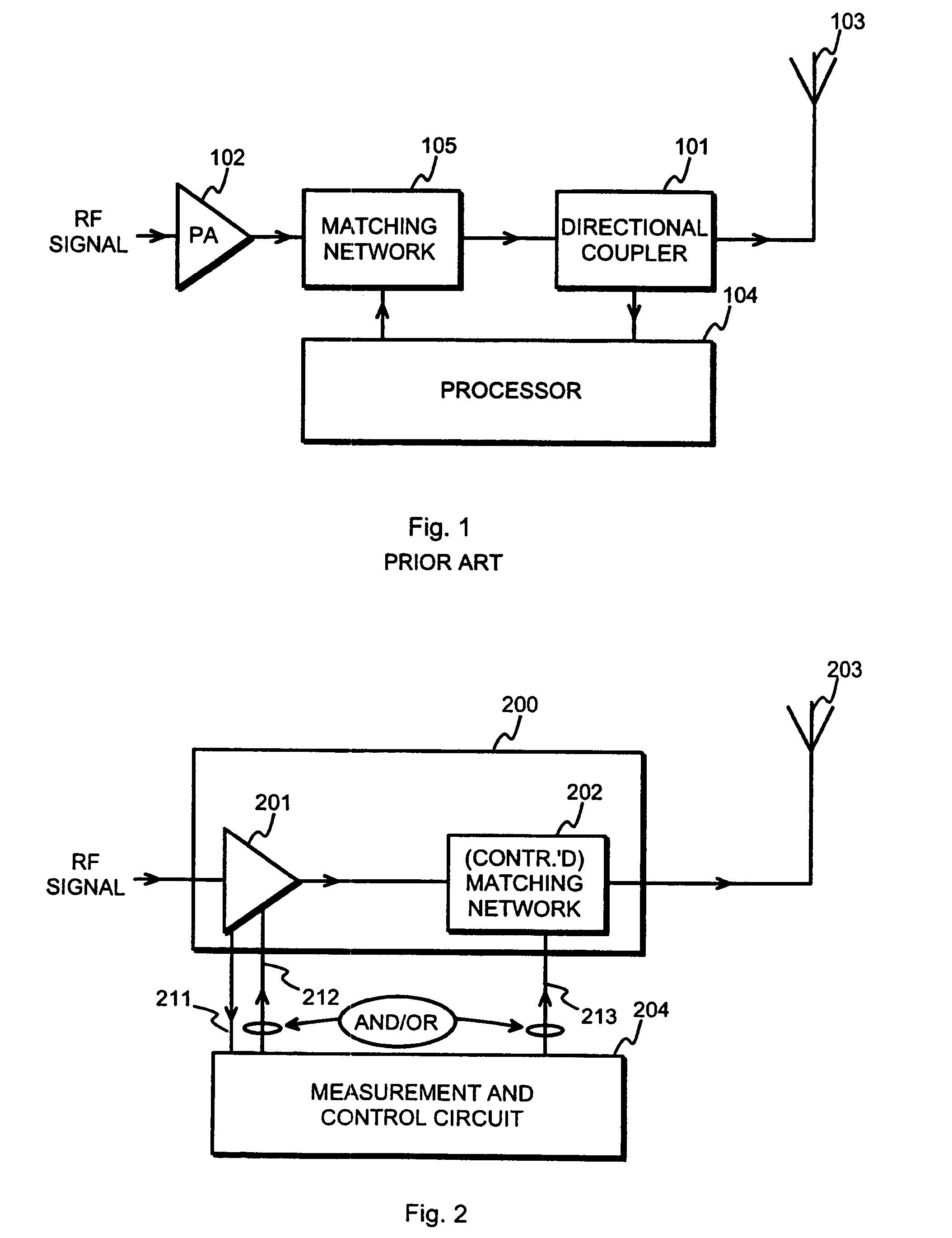
[0047]Regarding an issue of terminology, in the technological field of radio transmitters and especially transmitters in portable radio devices it has become customary to use the terms “power amplifier” and “PA” to designate an entity that comprises both an amplifying part and an impedance matching network that matches the output impedance of the amplifying component to a predetermined value. This is a further development from the practice of the early 1990's, according to which a single, individually packaged large transistor could be a “PA”—in present-day termi...


PUM


Abstract

A method and an arrangement for detecting impedance mismatch between an output of a radio frequency amplifier (200, 901, 911, 921, 1101) which has an amplifying component (201, 301, Q46, 701, 801) and an input of a load (203, 302) coupled to the output of the radio frequency amplifier having: first monitoring means (401) to monitor a measurable electric effect (311) at a side of the amplifying component (201, 301, Q46, 701, 801) other than the load (203, 302) and to produce a first measurement signal (411). Second monitoring means (402) monitor a measurable electric effect (312) between the amplifying component (201, 301, Q46, 701, 801) and the load (203, 302) and produce a second measurement signal (412). Decision-making means (204, 902, 912, 923, 1102) receive said first (411) and second (412) measurement signals and decide, whether said first and second measurement signals together indicate impedance mismatch.

Description

CROSS REFERENCE TO RELATED APPLICATIONS[0001]This application claims priority under 35 USC §119 to Finnish Patent Application No. 20021861 filed on Oct. 18, 2002.TECHNICAL FIELD[0002]The invention concerns generally the technology of radio frequency power amplifiers and their coupling to loads, particularly to transmission antennae. Especially the invention concerns the technology of detecting an impedance mismatch condition between a radio frequency power amplifier and an antenna coupled thereto.BACKGROUND OF THE INVENTION[0003]A power amplifier is essentially the last stage of a transmitter before a connection to a load, which in a radio transmitter means a transmitting antenna. Preceding stages of the transmitter produce a radio frequency signal by modulating a radio frequency carrier with a lower-frequency payload signal. The task of the power amplifier is to amplify the produced radio frequency signal enough so that directing it in amplified form to a transmitting antenna will ...

Claims


Application Information

Patent Timeline
IPC IPC(8): H03F1/52H03F1/00H03F1/56H04B1/04
CPCH03F1/52H03F1/56H04B1/0466H04B1/0458
Inventor VINTOLA, VILLE
Owner III HLDG 3
Why Eureka
Try Eureka