Mobile communication

Inactive Publication Date: 2006-06-06
NOKIA CORP
View PDF18 Cites 130 Cited by
  • Summary
  • Abstract
  • Description
  • Claims
  • Application Information

AI Technical Summary

Benefits of technology

[0011]a detuning switch for grounding the radiating body at a particular point between the feed po

Problems solved by technology

This naturally consumes power, causes possibly inconvenient amounts of heat dissipation and also may harm the circuitry connected to the other antenna that unintentionally captures the radio signals.
Due to portability requirements, the size o

Method used


Image

  • Mobile communication
  • Mobile communication
  • Mobile communication

Examples


Embodiment Construction

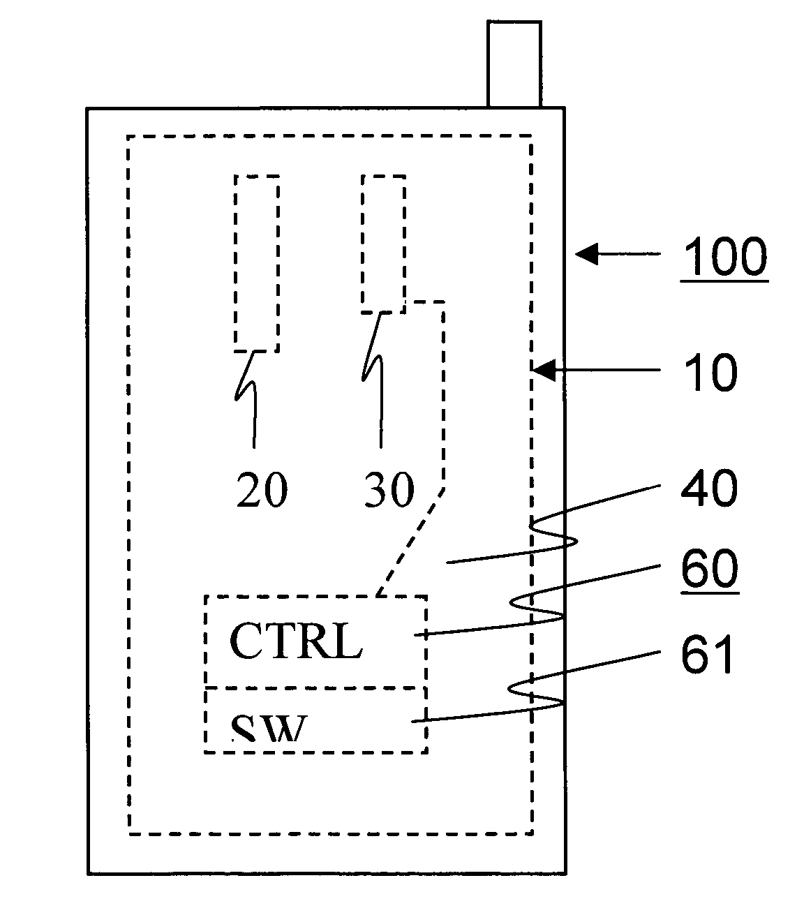
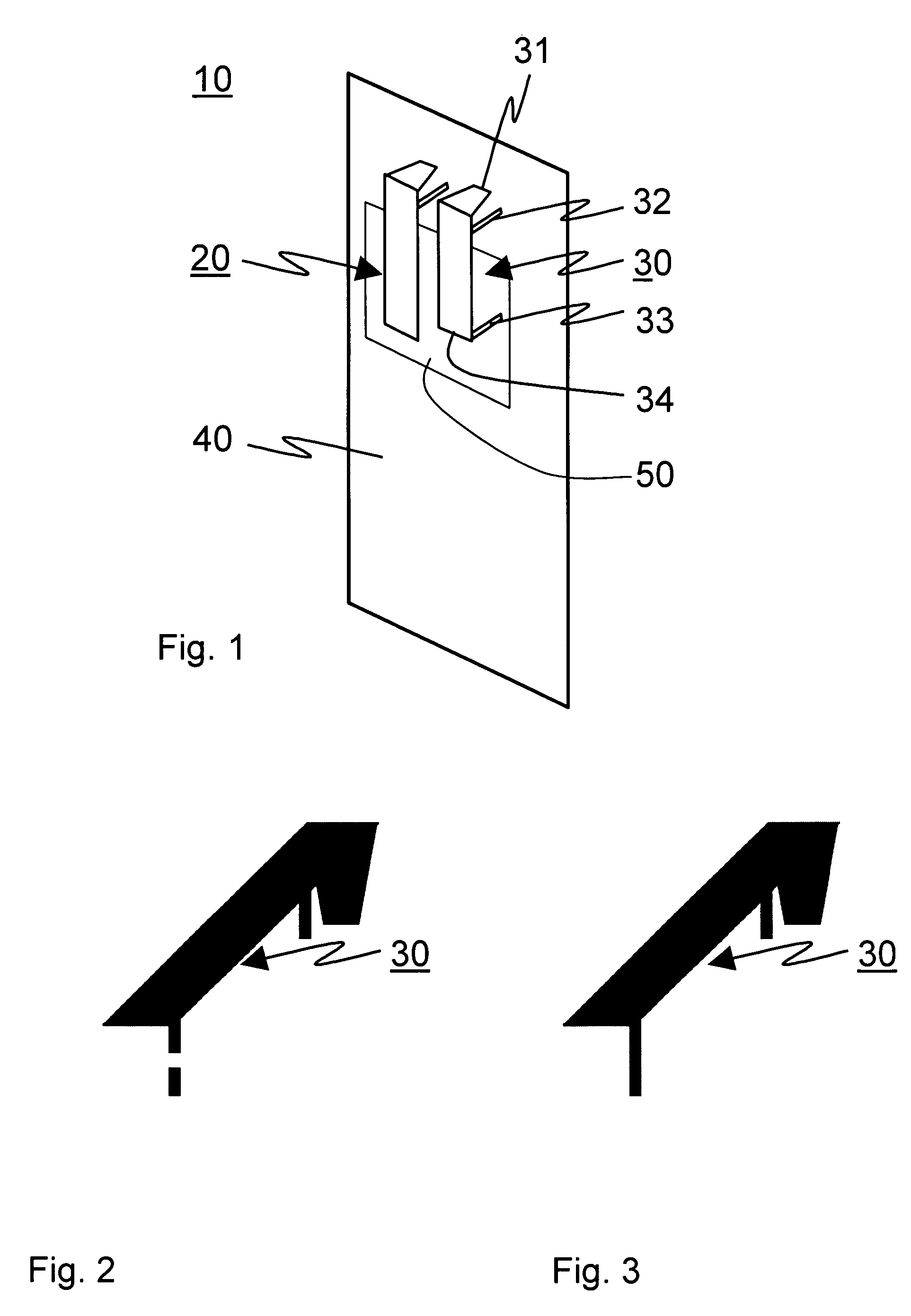
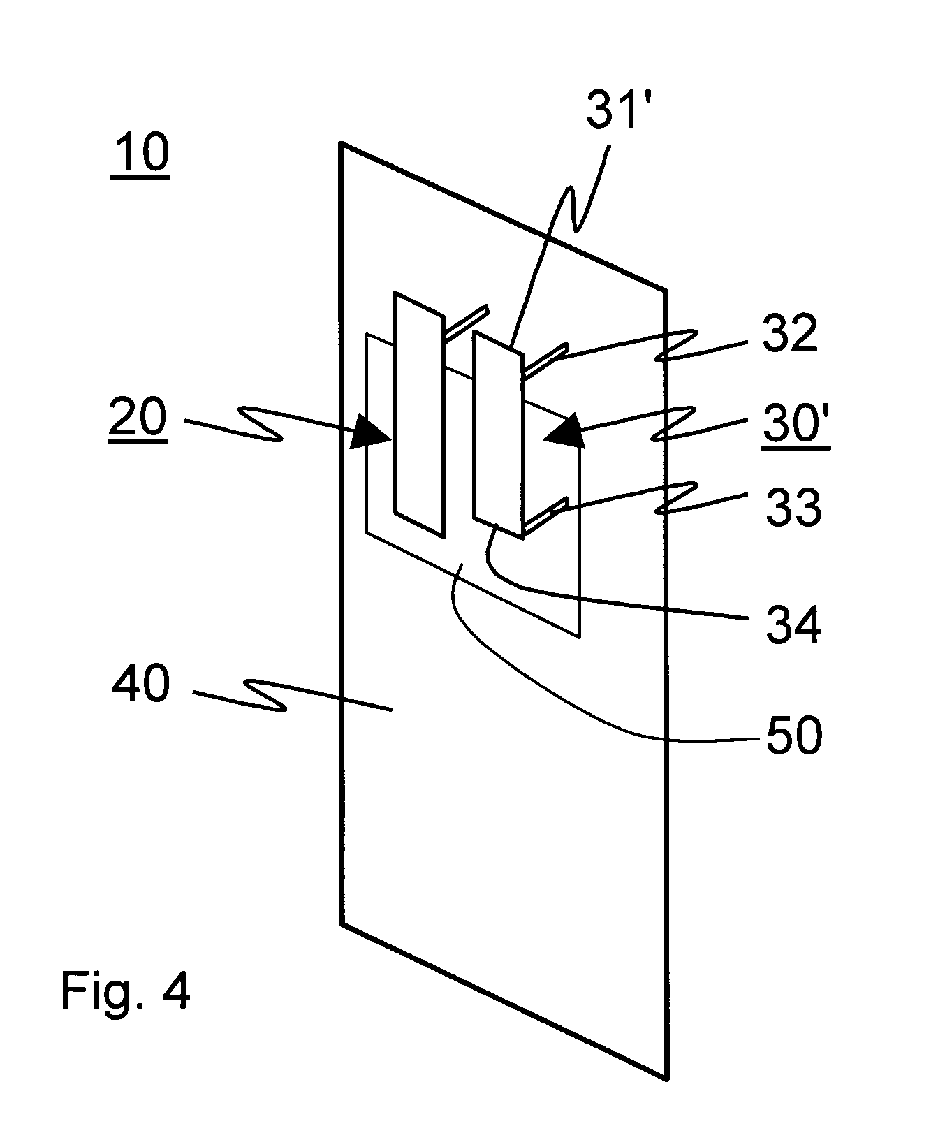
[0051]FIG. 1 shows a schematic drawing of an antenna arrangement 10 according to a preferred embodiment. The antenna arrangement 10 comprises a first PIFA antenna 20 and a second PIFA antenna 30 fixed to a circuit board 40. The second PIFA antenna comprises an elongated radiator 31 which is a substantially flat band that is connected in its first end to the circuit board 40 in a normal to the plane of the circuit board 40 and bent so that for most of its length the radiator 31 is parallel with the circuit board 40. The circuit board conducts feed signals to the antennas 20 and 30 and also forms a ground plane 50 for them. The arrangement 10 comprises a signal feed to the radiator 31 near the first end, connected to the part of the radiator that is substantially parallel with the circuit board 40. At its extreme end opposite to the first end, the radiator has a second end 34. A detuning switch or shorting switch 33, here illustrated as a shorting pin, is positioned at the second end ...


PUM


Abstract

An antenna arrangement for dual mode radio devices such as WCDMA/GSM or Bluetooth radio devices. The arrangement contains two antennas close to each other, where a shorting switch is used at an open end of one antenna to increase isolation by effectively converting the one antenna from a quarter wave length antenna to a half wave length antenna when not needed in order to improve the efficiency of the other antenna. The shorting switch is typically a MEMS switch and the antennas are typically PIFA antennas. A radio device containing the arrangement has also been disclosed.

Description

FIELD OF THE INVENTION[0001]This invention relates to mobile communication. The invention relates particularly, but not exclusively, to reduction of coupling between different antennas in one portable radio device.BACKGROUND OF THE INVENTION[0002]Mobile telephones have drastically developed during past decade so that in the near future, the most developed ones will provide 2 G, 3 G and Low Power Radio Frequency (LPRF) radio communications all in the same portable device. Typically, these devices are designed to be hand held, but other form factors such as wristwatch type and wearable devices may also emerge. Common to them all, the number of antennas needed in a single device is likely to grow to two or three.[0003]An antenna radiates electromagnetic waves with a power that is a function of its electric feed signal's power and frequency. An antenna has a resonant frequency at which it has the highest gain, which is radiation power. The highest gain not only affects the transmission ...

Claims


Application Information

Patent Timeline
IPC IPC(8): H04M1/00H01Q1/24H01Q1/52H01Q9/04H01Q21/28
CPCH01Q1/243H01Q1/52H01Q21/28H01Q9/0442H01Q9/0421
Inventor WANG, HANYANGZHENG, MINGGOWARD, JASON
Owner NOKIA CORP
Why Eureka
Try Eureka