Dual receiver/transmitter radio devices with choke

a radio device and receiver technology, applied in the field of wireless communication systems, can solve the problems of not being economically feasible to lay new fibers, not being able to extend the reach of optical fibers to sparsely populated areas, and being limited in the application of optical fibers, so as to increase the rigidity of the overall device/system

Active Publication Date: 2014-09-16
UBIQUITI INC
View PDF282 Cites 128 Cited by
  • Summary
  • Abstract
  • Description
  • Claims
  • Application Information

AI Technical Summary

Benefits of technology

[0015]In general, described herein are devices and systems, and methods of using them, for point-to-point transmission / communication of high bandwidth signals. For example, described herein are radio devices and systems including dual high-gain reflector antennas. A typical radio device may include a pair of reflectors (e.g., parabolic reflectors) that are adjacent to each other and configured so that one of the reflectors is dedicated for sending / transmitting information, and the adjacent reflector is dedicated for receiving information. Both reflectors may be in a fixed configuration relative to each other so that they are aligned to send / receive in parallel. In many variations the two reflectors are formed of a single housing, so that the parallel alignment is fixed, and reflectors cannot lose alignment. The housing forming or holding the antenna is this fixed parallel alignment may be adapted to prevent disruption of the alignment, for example, by increasing the rigidity of the overall device / system.

Problems solved by technology

However, there are limitations to the application of optical fibers.
Because laying optical fibers in the field can require a large initial investment, it is not cost effective to extend the reach of optical fibers to sparsely populated areas, such as rural regions or other remote, hard-to-reach areas.
Moreover, in many scenarios where a business may want to establish point-to-point links among multiple locations, it may not be economically feasible to lay new fibers.
However, currently available wireless technologies for long-range, point-to-point connections encounter many problems, such as limited range and poor signal quality.
Conventional radio devices, including radio devices having parabolic reflectors, suffer from a variety of problems, including difficulty in aligning with an appropriate receiver, monitoring and switching between transmitting and receiving functions, avoiding interference (including reflections and spillover from adjacent radios / antennas), and complying with regulatory requirements without negatively impacting function.
The resonators on conventional filters are limited because a higher Q factor and increased performance stability may only be achieved by increasing the internal volume of the filter cavities.
While generating attenuation poles at specific frequencies in the filter response is well known in standard multi-pole filters, the polarization-preserving characteristic is not always fully realized.

Method used


Image

  • Dual receiver/transmitter radio devices with choke
  • Dual receiver/transmitter radio devices with choke
  • Dual receiver/transmitter radio devices with choke

Examples


Embodiment Construction

[0225]Described herein are radio devices for point-to-point and / or point-to-multipoint transmission of high bandwidth radio signals. These devices may include radio apparatuses (devices / systems) used for high-speed, long-range wireless communication.

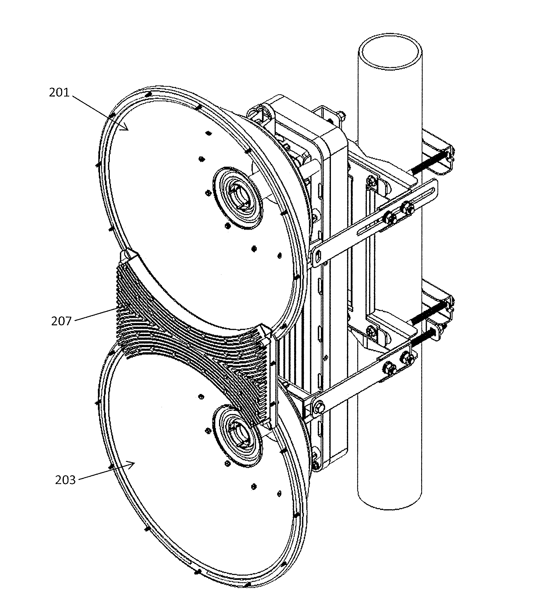
[0226]In general, these radios may include a dedicated transmit reflector (connected to one or more transmitters), and a dedicated receiver reflector (connected to one or more receivers). The dedicated transmit and receive reflectors may be held in a fixed relationship with each other. In some variations the devices and systems may also be configured so that the circuitry for the radio is held on a single board, which connects to both the transmitter antenna feed, connected to the transmitter reflector, and the receiver antenna feed, connected to the receiver reflector. The two reflectors may be adapted for use in any appropriate frequency range, including, e.g., the 5 GH frequency range, the 11 GHz frequency range, the 13 GHz frequency ...


PUM


Abstract

Wireless radio apparatuses for point-to-point or point-to-multipoint transmission / communication of high bandwidth signals having dual receivers and transmitters. Radio devices and systems may include a pair of reflectors separated by an isolation choke boundary. The device may be configured to operate in any appropriate band (e.g., a 5 GHz band, a 24 GHz band, etc.) and may simultaneously transmit and receive with minimal crosstalk. The isolation choke boundary may have ridges that extend between the first and second parabolic reflectors to a height that may be tuned to the band. The isolation choke boundary provides greater than 10 dB isolation between the first and the second parabolic reflectors may be in a fixed configuration relative to each other so that they are aligned to send / receive in parallel. The two reflectors may be formed of a single housing, with fixed parallel alignment.

Description

CROSS REFERENCE TO RELATED APPLICATIONS[0001]This patent application claims priority as a continuation-in-part to U.S. patent application Ser. No. 13 / 843,205, titled “RADIO SYSTEM FOR LONG-RANGE HIGH-SPEED WIRELESS COMMUNICATION”, and filed on Mar. 15, 2013. The entire contents of this application are herein incorporated by reference in its entirety.[0002]This patent application also claims priority to U.S. Provisional Patent Application No. 61 / 760,387, titled “DUAL POLARIZED WAVEGUIDE FILTER”, and filed on Feb. 4, 2013; U.S. Provisional Patent Application No. 61 / 760,381, titled “FULL DUPLEX ANTENNA”, and filed on Feb. 4, 2013; U.S. Provisional Patent Application No. 61 / 762,814, titled “RADIO SYSTEM FOR LONG-RANGE HIGH-SPEED WIRELESS COMMUNICATION”, and filed on Feb. 8, 2013; U.S. Provisional Patent Application No. 61 / 891,877, titled “RADIO SYSTEM FOR LONG-RANGE HIGH-SPEED WIRELESS COMMUNICATION”, and filed on Oct. 16, 2013; and U.S. Provisional Patent Application No. 61 / 922,741, ti...

Claims


Application Information

Patent Timeline
Patent Type & Authority Patents(United States)
IPC IPC(8): H01Q19/10H01Q19/12H01Q19/18
CPCH01Q19/18H01Q19/12H01Q1/42H01Q1/525H01Q15/14H01Q1/526H01Q1/1228H01Q19/13H01Q19/134H01Q15/16
Inventor SANFORD, JOHN R.SCHULZ, GARY D.
Owner UBIQUITI INC
Why Eureka
Try Eureka