Heat dissipation system

Inactive Publication Date: 2007-04-12
DELTA ELECTRONICS INC
View PDF22 Cites 14 Cited by
  • Summary
  • Abstract
  • Description
  • Claims
  • Application Information

AI Technical Summary

Benefits of technology

[0008] The invention provides a heat dissipation system including a plurality of fans, each of which has a cont

Problems solved by technology

Further, the wiring arrangement and the addition of the controller

Method used


Image

  • Heat dissipation system
  • Heat dissipation system
  • Heat dissipation system

Examples


Embodiment Construction

[0014] The following description is of the best-contemplated mode of carrying out the invention. This description is made for the purpose of illustrating the general principles of the invention and should not be taken in a limiting sense. The scope of the invention is best determined by reference to the appended claims.

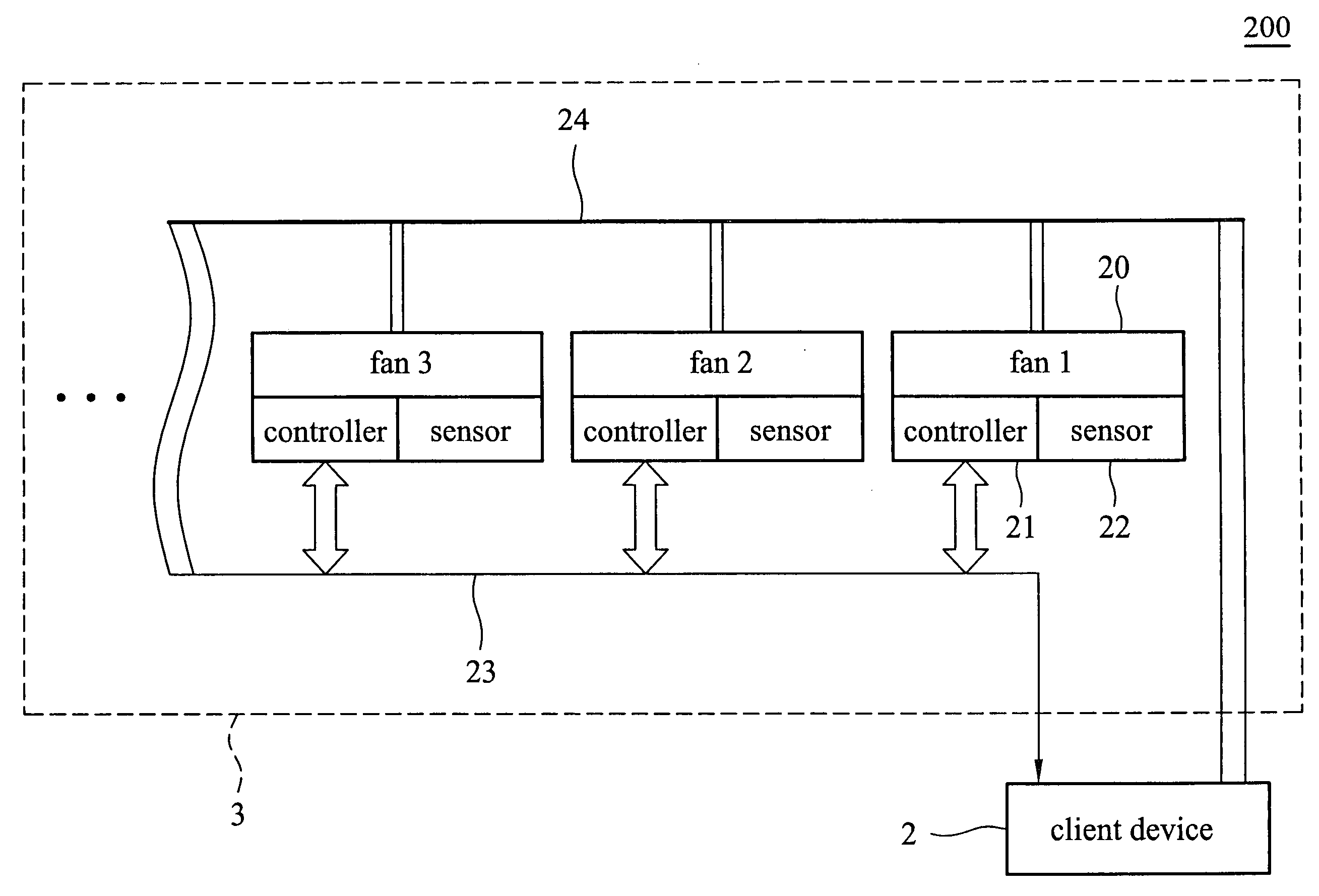
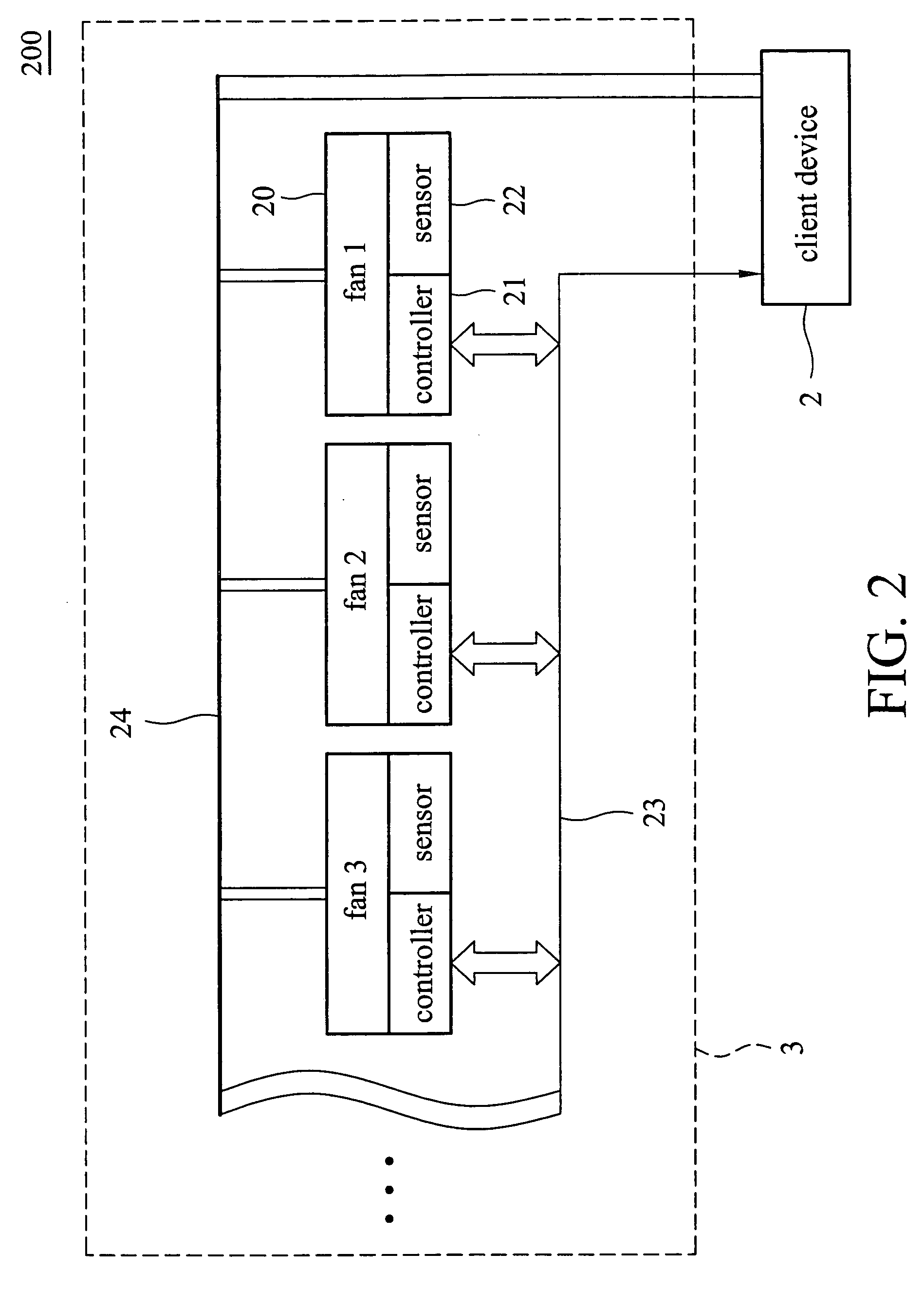
[0015]FIG. 2 shows a heat dissipation system 200 according to an embodiment of the invention. The heat dissipation system 200 has a fan module 3 and a client device 2.

[0016] The fan module 3 includes at least two fans 20, for example, three fans 20, as shown in FIG. 2. Each of the fans 20 has a controller 21 and a sensor 22. The controllers 21 in the fans 20 are connected with each other. In this embodiment, the fans 20 are electrically connected to the client device 2 via a transmission device 23 and a power line 24 so as to receive a control signal and power therefrom and feed back operation details of each fan 20 thereto.

[0017] The controllers 21 can be implemen...


PUM


Abstract

A heat dissipation system includes a fan module and a client device. The fan module includes at least two fans, each of which has a controller and a sensor. The client device is electrically connected to the controllers of the fans and generates a first control request and a second control request to allow the fans of the fan module to respectively operate in synchronous and asynchronous modes. The dissipation system allows the fans to be switched between these modes in accordance with the environment.

Description

[0001] This Non-provisional application claims priority under U.S.C.§ 119(a) on Patent Application No(s). 094135035 filed in Taiwan, Republic of China on Oct. 7, 2005, the entire contents of which are hereby incorporated by reference. BACKGROUND OF THE INVENTION [0002] 1. Field of the Invention [0003] The invention relates to a heat dissipation system, and more particularly to a heat dissipation system having synchronous and asynchronous operating modes. [0004] 2. Description of the Related Art [0005] To dissipate heat, at least one heat dissipation system is usually built into electronic apparatuses according to the size thereof. FIG. 1 shows a conventional heat dissipation system 100 including several fans 10 and a controller 1, one end of which is electrically connected to a client device 2 and the other end is electrically connected to the fans 10. The client device 2 provides power to the fans 10 via the controller 1. The controller 1 transmits a predetermined speed control sig...

Claims


Application Information

Patent Timeline
IPC IPC(8): H02P7/08
CPCH05K7/20209
Inventor WEI, CHIA-PINCHEN, CHIEN-HUACHEN, YI-LUNHUANG, WEN-SHI
Owner DELTA ELECTRONICS INC
Why Eureka
Try Eureka