Multi-zone, single trip well completion system and methods of use

a well completion system and single-trip technology, applied in the direction of fluid removal, wellbore/well accessories, sealing/packing, etc., can solve the problems of large amount of well completion costs, time that it takes to remove tools, and large amount of debris, so as to facilitate assembly hanging and prevent or reduce the amount of debris

Active Publication Date: 2007-04-19
BAKER HUGHES INC
View PDF11 Cites 56 Cited by
  • Summary
  • Abstract
  • Description
  • Claims
  • Application Information

AI Technical Summary

Benefits of technology

[0051] A production zone assembly 108 may comprise an automatic locating assembly 106 to locate positively the completion system in its several conditions, such as, but not limited to, a “Frac / Set Down” position, a “Pickup” position, and a “Run-in” position. The automatic locating assembly or “autolocator”106 preferably comprises a debris barrier, such as, but not limited to, a molded rubber cup positioned above the autolocator 106 and engaging the casing or well bore for preventing or reducing the amount of debris from collecting in the autolocator 106. In addition, a quick union may be interposed between the production packer assembly 102 and the topmost production zone assembly 108 so the completion assembly 100 does not have to be rotated after the tool assembly 200 is positioned therein. Also in each production zone assembly 108, it is preferred to place a shear-out safety joint 109 (e.g., FIG. 5b) in case the completion system becomes stuck. A mechanical shear out safety joint or a hydraulically actuated safety joint may be employed. It is preferred to locate the safety joint above the first sealing system 110 and below the autolocator 106. A running groove may also be provided in each production zone assembly to facilitate hanging the assemblies off of the rig floor.

Problems solved by technology

One of the single biggest costs associated with completing a subterranean hydrocarbon well, such as a sub sea well, is the time that it takes to remove a tool or other well equipment from the well bore.
Depending on well depth, tripping time may account for the majority of well completion costs.

Method used


Image

  • Multi-zone, single trip well completion system and methods of use
  • Multi-zone, single trip well completion system and methods of use
  • Multi-zone, single trip well completion system and methods of use

Examples


Embodiment Construction

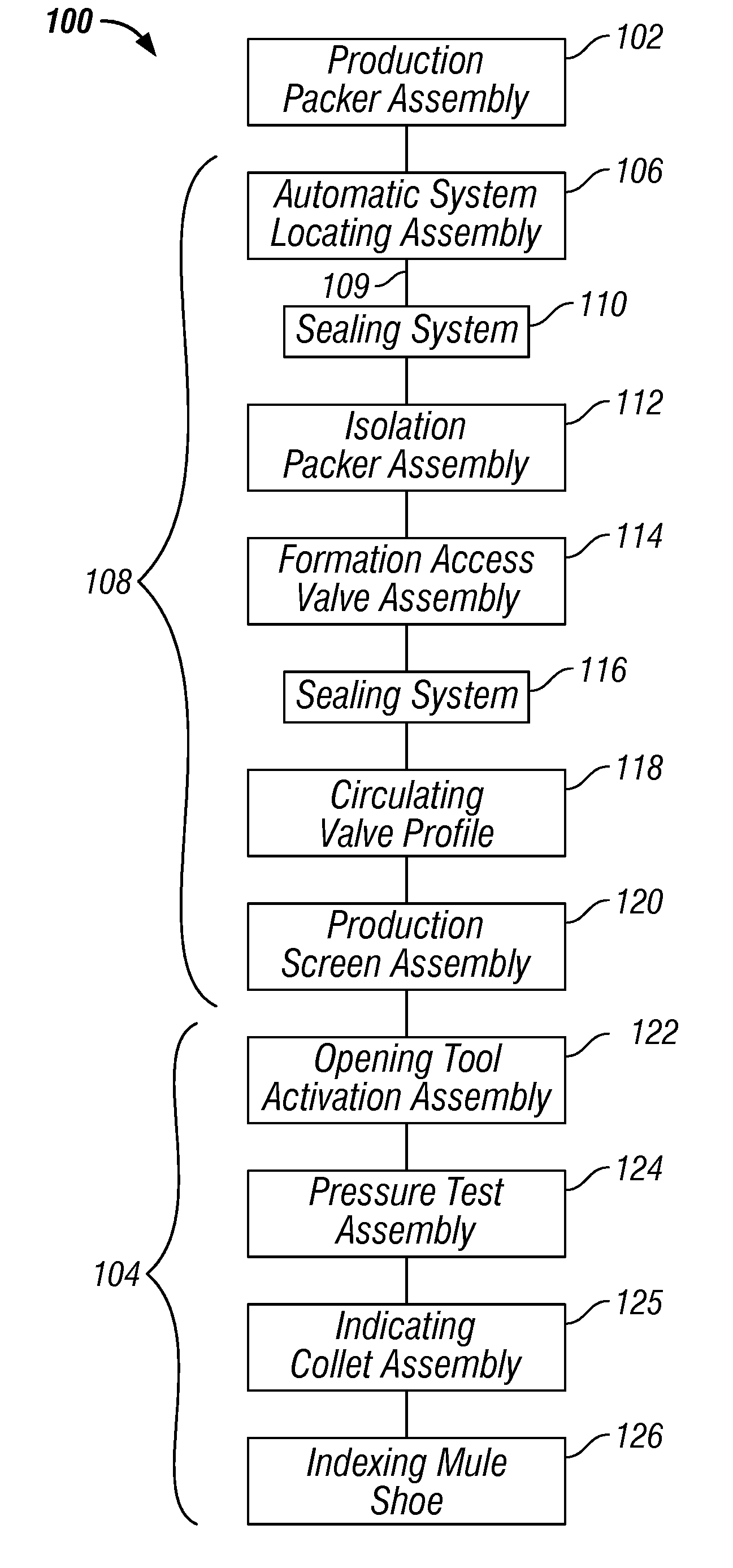
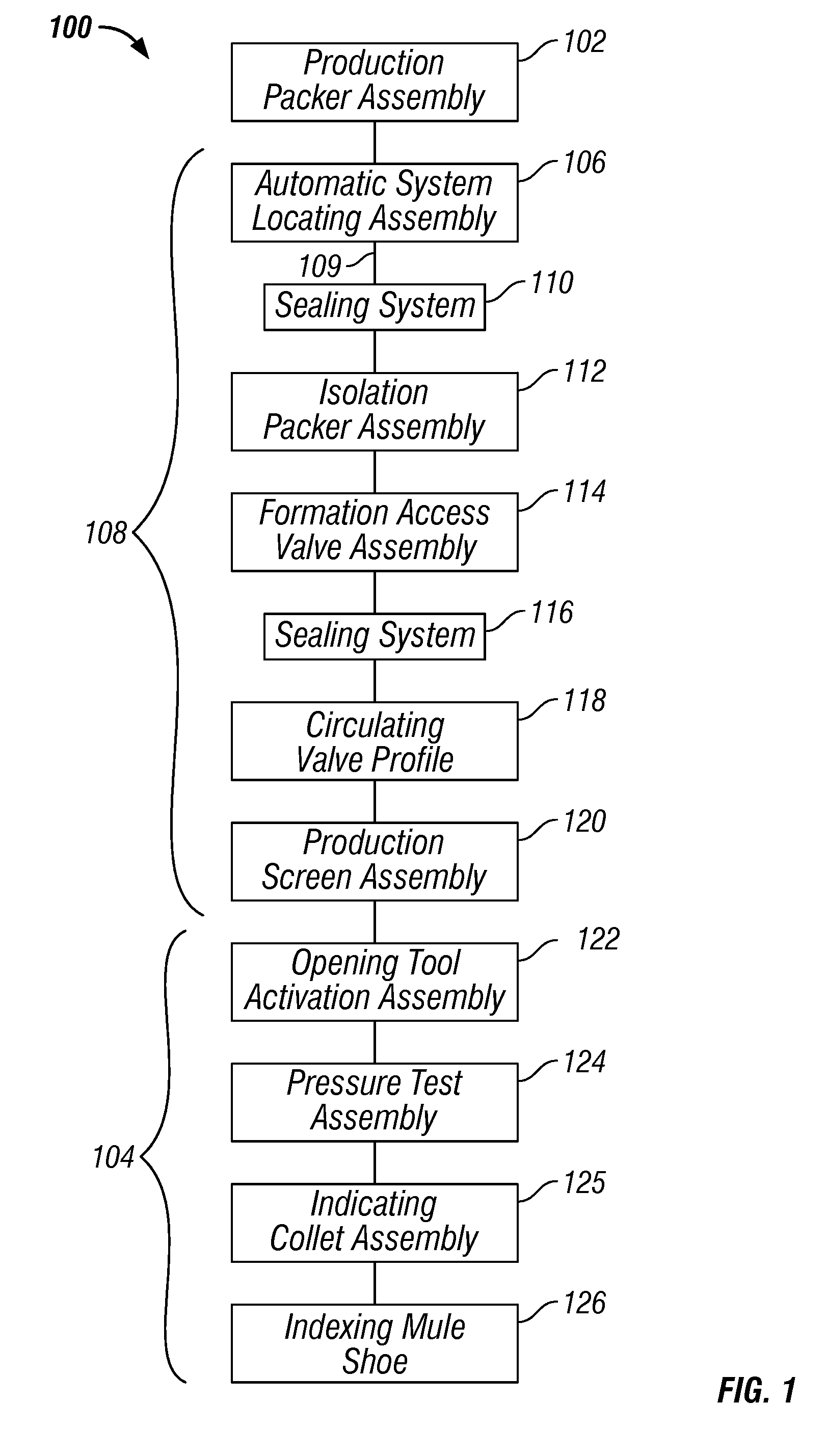
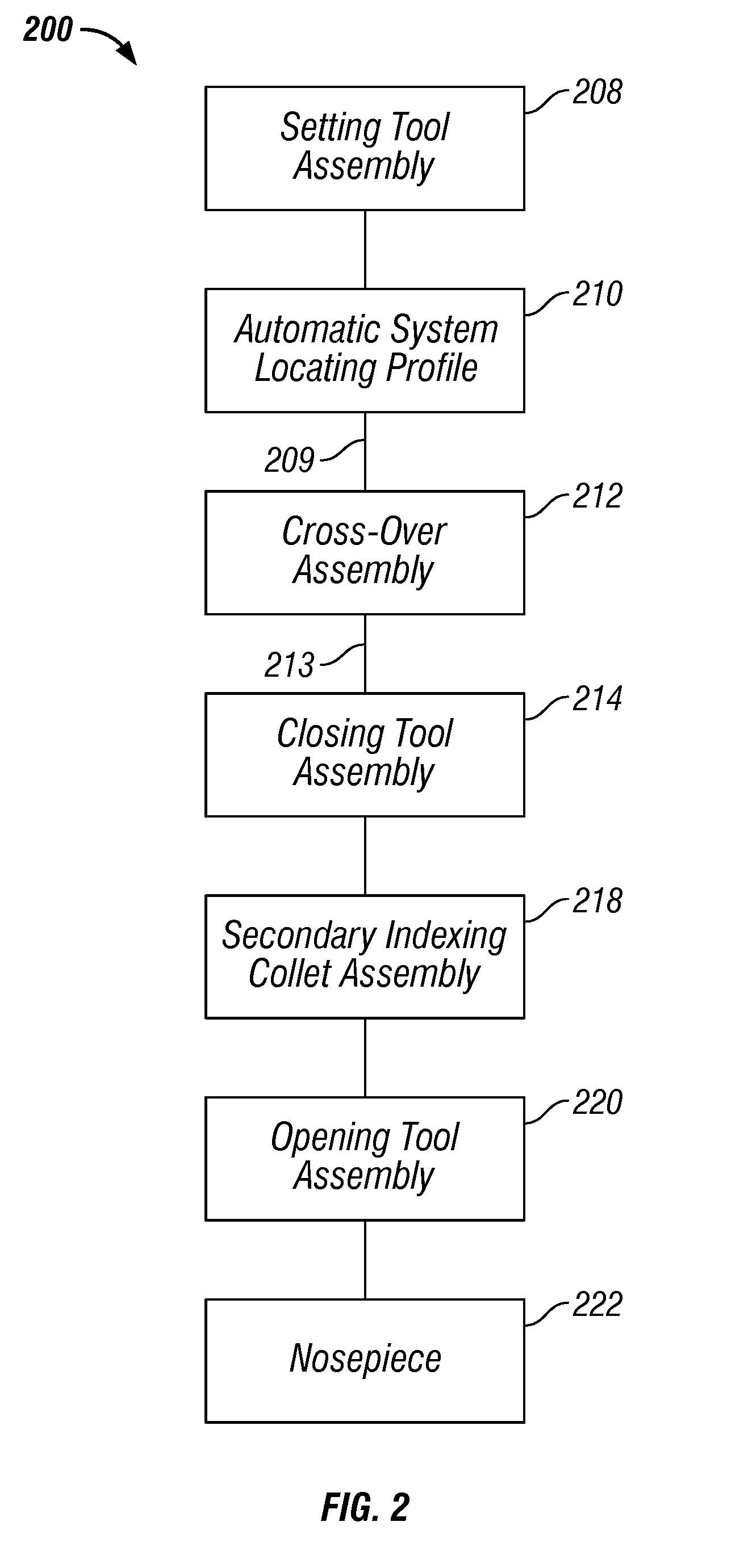
[0031] The Figures described above and the written description of specific structures and processes below are not intended to limit the scope of what Applicants have invented or the scope of protection for those inventions. The Figures and written description are provided to teach any person skilled in the art to make and use the inventions for which patent protection is sought. Those skilled in the art will appreciate that not all features of a commercial implementation of the inventions are described or shown for the sake of clarity and understanding. Persons of skill in this art also appreciate that the development of an actual commercial embodiment incorporating aspects of the present inventions will require numerous implementation-specific decisions to achieve the developer's ultimate goal for the commercial embodiment. Such implementation-specific decisions may include, and likely are not limited to, compliance with system-related, business-related, government-related and othe...


PUM


Abstract

An improved well completion system for completing two or more separate production zones in a well bore during a single downhole trip is disclosed. The improved completion system comprises a completion assembly comprising two or more production zone assemblies and a completion tool assembly. Each production zone assembly may comprise an automatic system locating assembly and at least two inverted seal systems for sealing against the tool assembly.

Description

CROSS REFERENCE TO RELATED APPLICATIONS [0001] This application for patent claims benefit of and priority from U.S. Provisional Patent Application Ser. No. 60 / 678,689, filed on May 6, 2005, and U.S. Provisional Patent Application Ser. No. 60 / 763,246, filed on Jan. 30, 2006.STATEMENT REGARDING FEDERALLY SPONSORED RESEARCH OR DEVELOPMENT [0002] Not applicable. REFERENCE TO APPENDIX [0003] Not applicable. BACKGROUND OF THE INVENTION [0004] 1. Field Of The Invention [0005] The inventions described herein relate generally to hydrocarbon well completion systems, and more particularly to a system for completing multiple production zones in a single trip. [0006] 2. Description of the Related Art [0007] One of the single biggest costs associated with completing a subterranean hydrocarbon well, such as a sub sea well, is the time that it takes to remove a tool or other well equipment from the well bore. Depending on well depth, tripping time may account for the majority of well completion cos...

Claims


Application Information

Patent Timeline
Patent Type & Authority Applications(United States)
IPC IPC(8): E21B43/14
CPCE21B23/006E21B33/12E21B34/06E21B34/063E21B43/08E21B43/14E21B43/26E21B34/14E21B43/04
Inventor WALKER, DAVID J.TURNER, DEWAYNE M.STOUT, GREGG W.CHRETIEN, TODDBLACKLER, CHRISTOPHER L.ROBBINS, JACK
Owner BAKER HUGHES INC
Why Eureka
Try Eureka