Ink-jet image forming apparatus to maintain a nozzle unit

a technology of forming apparatus and nozzle unit, which is applied in the direction of printing, other printing apparatus, etc., can solve the problems of reducing printing quality, distorted ejecting direction of ink, and reducing the life of ink in the nozzle uni

Inactive Publication Date: 2007-04-26
SAMSUNG ELECTRONICS CO LTD
View PDF24 Cites 8 Cited by
  • Summary
  • Abstract
  • Description
  • Claims
  • Application Information

AI Technical Summary

Benefits of technology

[0007] The present general inventive concept provides an ink-jet image forming apparatus in which a nozzle unit of an array ink-jet head is effectively wiped.

Problems solved by technology

Due to the solidified ink or foreign substances, an ink ejecting direction may be distorted and printing quality may be lowered.
In addition, ink in the nozzle unit is evaporated and the nozzle unit is clogged.
Unlike the shuttle type ink-jet head which is driven in a main scanning direction with reciprocation, since the array ink-jet head ejects ink in a fixed location, when a portion of a plurality of nozzles is clogged or an ink ejecting direction is distorted by foreign substances, it is difficult to complement the problem, that is, difficult to clean the array ink-jet head.

Method used


Image

  • Ink-jet image forming apparatus to maintain a nozzle unit
  • Ink-jet image forming apparatus to maintain a nozzle unit
  • Ink-jet image forming apparatus to maintain a nozzle unit

Examples


Embodiment Construction

[0042] Reference will now be made in detail to the embodiments of the present general inventive concept, examples of which are illustrated in the accompanying drawings, wherein like reference numerals refer to the like elements throughout. The embodiments are described below in order to explain the present general inventive concept by referring to the figures.

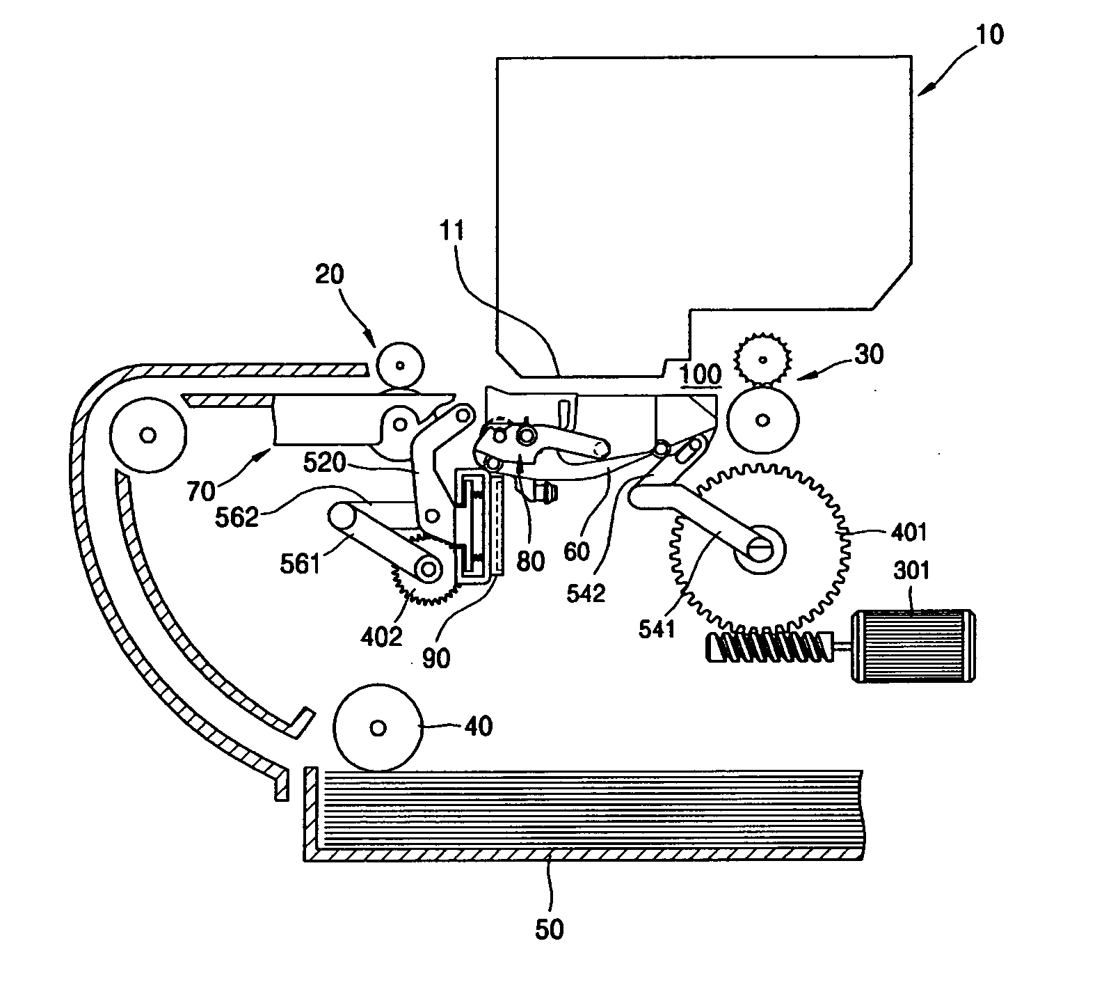
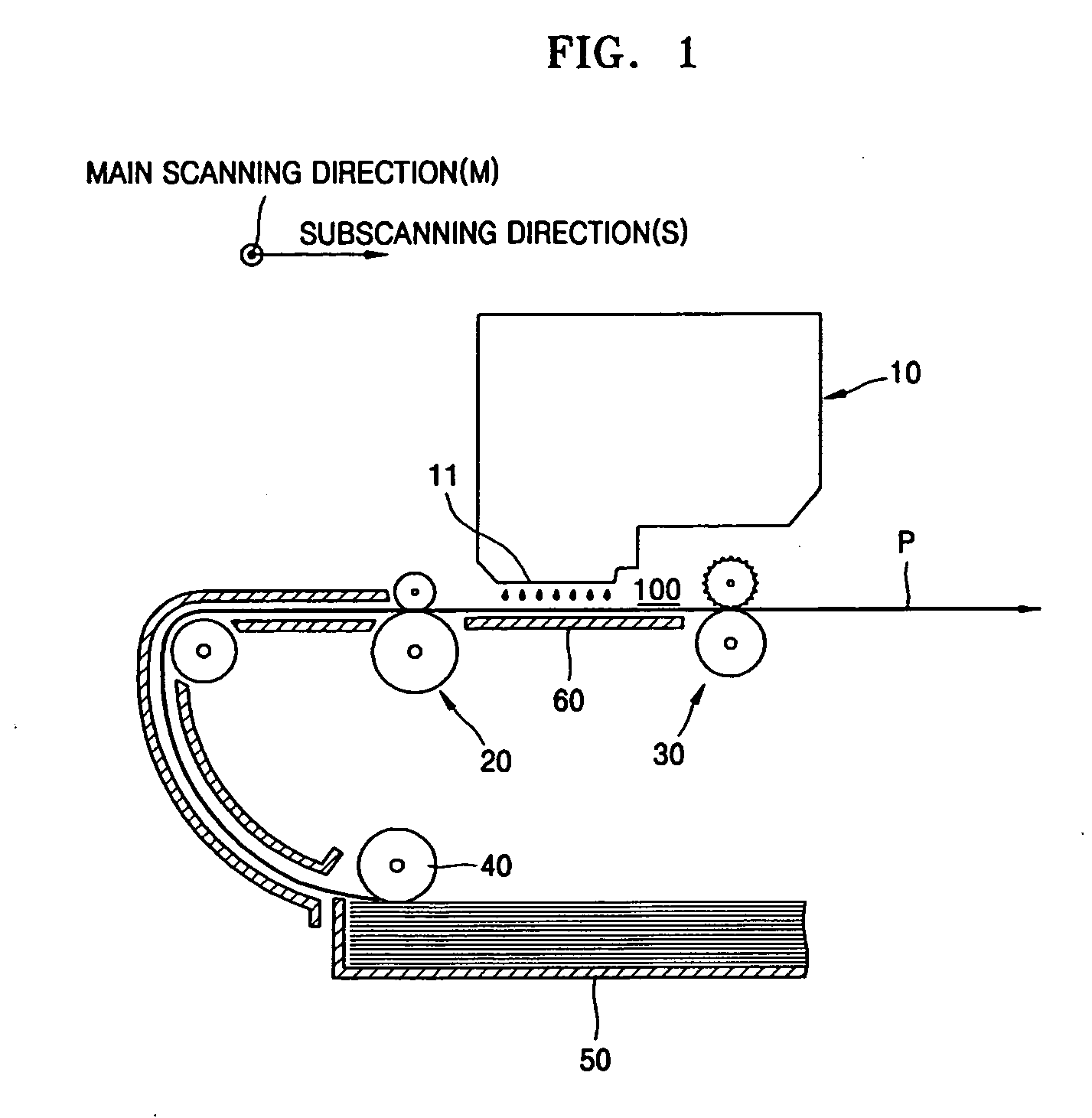
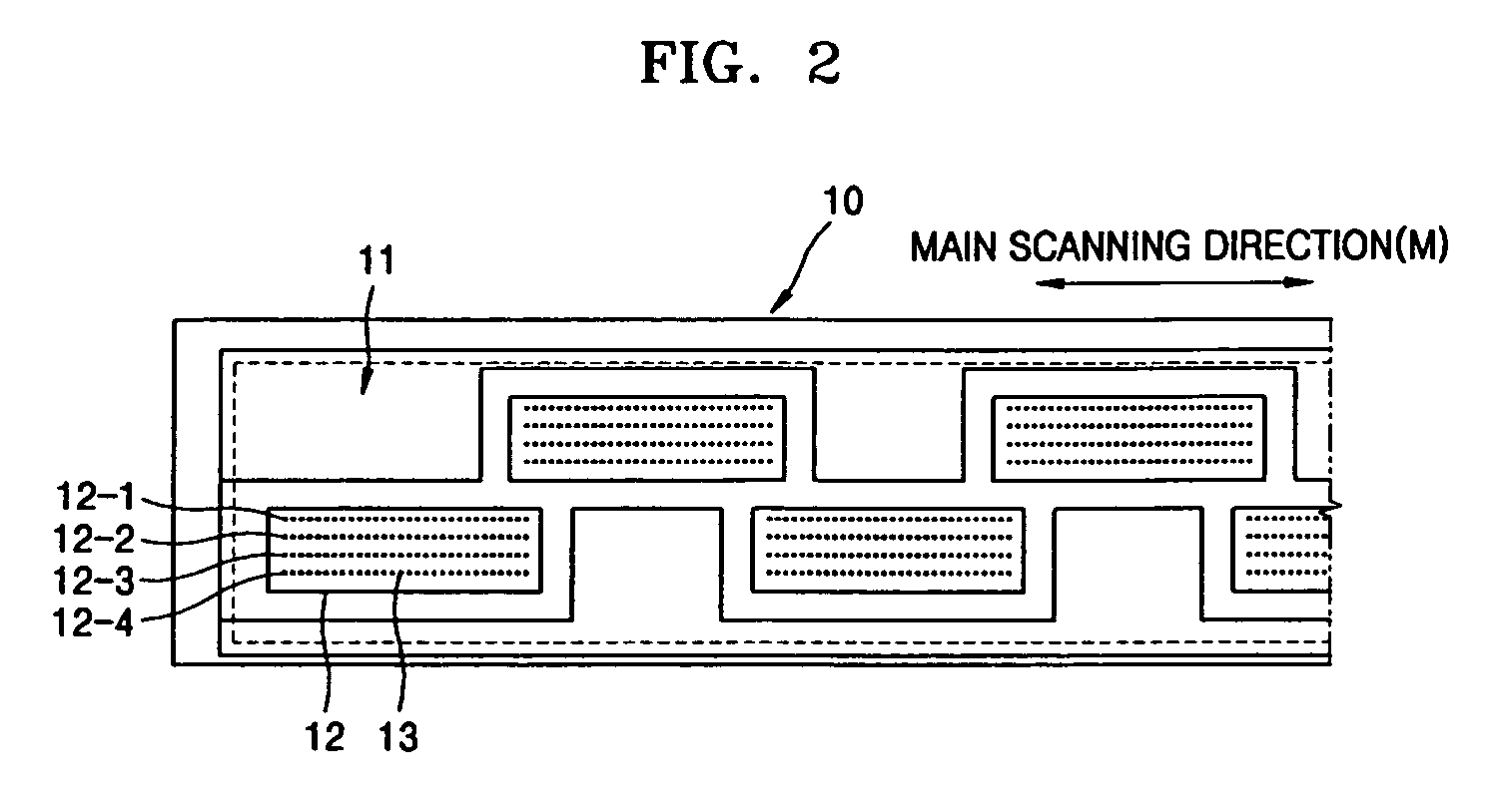
[0043]FIG. 1 is a view illustrating an ink-jet image forming apparatus according to an embodiment of the present general inventive concept. Referring to FIG. 1, a printing medium, such as a sheet of paper P picked up by a pickup roller 40 from a paper feeding cassette 50 is conveyed by a conveying unit 20 in a sub-scanning direction S, i.e., a paper feeding direction of the paper P. An ink-jet head 10 is installed in an upward direction of the paper P. The ink-jet head 10 prints an image on the paper P by ejecting ink on the paper P in a fixed location using a nozzle unit 11. The paper P is discharged by an exhaust (dischargin...


PUM


Abstract

An ink-jet image forming apparatus includes an ink-jet head having a nozzle unit having a length in a main scanning direction corresponding to a width of a printing medium, a platen to face the nozzle unit, to support a rear side of the printing medium, and to form a paper conveying path, and a wiping unit to clean the nozzle unit. The platen has a printing location in which the paper conveying path is formed, a maintenance location different from the printing location, and a replacement location in which the wiping unit is replaced.

Description

CROSS-REFERENCE TO RELATED APPLICATIONS [0001] This application claims priority under U.S.C. §119(a) from Korean Patent Application No. 10-2005-0099335, filed on Oct. 20, 2005, in the Korean Intellectual Property Office, the disclosure of which is incorporated herein in its entirety by reference. BACKGROUND OF THE INVENTION [0002] 1. Field of the Invention [0003] The present general inventive concept relates to an ink-jet image forming apparatus, and more particularly, to an ink-jet image forming apparatus having an ink-jet head, a nozzle unit having the length in a main scanning direction corresponding to a width of a printing medium, and a wiping unit to clean the nozzle unit. [0004] 2. Description of the Related Art [0005] In general, ink-jet image forming apparatuses are apparatuses for ejecting ink on a paper transferred to a subscanning direction from an ink-jet head (shuttle type ink-jet head) which is driven to reciprocate in a main scanning direction and forming an image. T...

Claims


Application Information

Patent Timeline
Patent Type & Authority Applications(United States)
IPC IPC(8): B41J2/165
CPCB41J2/16544B41J2/16535B41J2/16585B41J11/02B41J11/06
Inventor JUNG, YOUN-GUNPARK, JIN-HOHA, DONG-WOO
Owner SAMSUNG ELECTRONICS CO LTD
Why Eureka
Try Eureka