Liquid discharge head and method for manufacturing the same

a technology of liquid discharge head and discharge port, which is applied in the direction of printing, inking apparatus, etc., can solve the problems of difficult to difficult to properly wipe the discharge port, and limited the density of the plurality of discharge ports of the liquid discharge head, etc., to achieve efficient wipe, efficient performance, and ensure reliability against long-term use

Active Publication Date: 2017-04-18
CANON KK
View PDF5 Cites 0 Cited by
  • Summary
  • Abstract
  • Description
  • Claims
  • Application Information

AI Technical Summary

Benefits of technology

[0010]According to the present invention, in the pressure-chamber-forming member having a joint surface, which is joined to the discharge-port-forming member, the volumes of the plurality of pressure chambers can be varied without changing the planar size of the pressure-chamber-forming member by forming the pressure chambers by arbitrarily changing the recess depths from the joint surface. As a result, a dense arrangement of the discharge ports, each of which is in communication with the corresponding pressure chamber, can be easily realized, and liquid droplets of a plurality of sizes can be discharged in the same pressure-chamber-forming member.
[0011]Since the pressure chambers whose depths from the joint surface of the pressure-chamber-forming member, which is joined to the discharge-port-forming member, are different from each other are formed, a front surface (discharge-port surface) of the discharge-port-forming member that is formed on the joint surface is also flat surface. Thus, an operation of wiping the discharge-port surface to which the liquid has adhered can be efficiently performed, and the reliability against long-term use can be ensured.
[0012]According to the present invention, a liquid discharge head in which the dense arrangement of discharge ports can be realized and in which the discharge-port surface can be efficiently wiped can be provided.

Problems solved by technology

Thus, in order to discharge a large liquid droplet, a pressure chamber having an area large enough to discharge the large liquid droplet needs to be formed, and the liquid discharge head has a limitation with regard to densely arranging a plurality of discharge ports.
Thus, in the case where the discharge-port surface has a difference in level, there have been problems in that it is difficult to properly wipe the discharge ports positioned at a lower level, and that it is difficult to ensure reliability against long-term use.

Method used


Image

  • Liquid discharge head and method for manufacturing the same
  • Liquid discharge head and method for manufacturing the same
  • Liquid discharge head and method for manufacturing the same

Examples


first embodiment

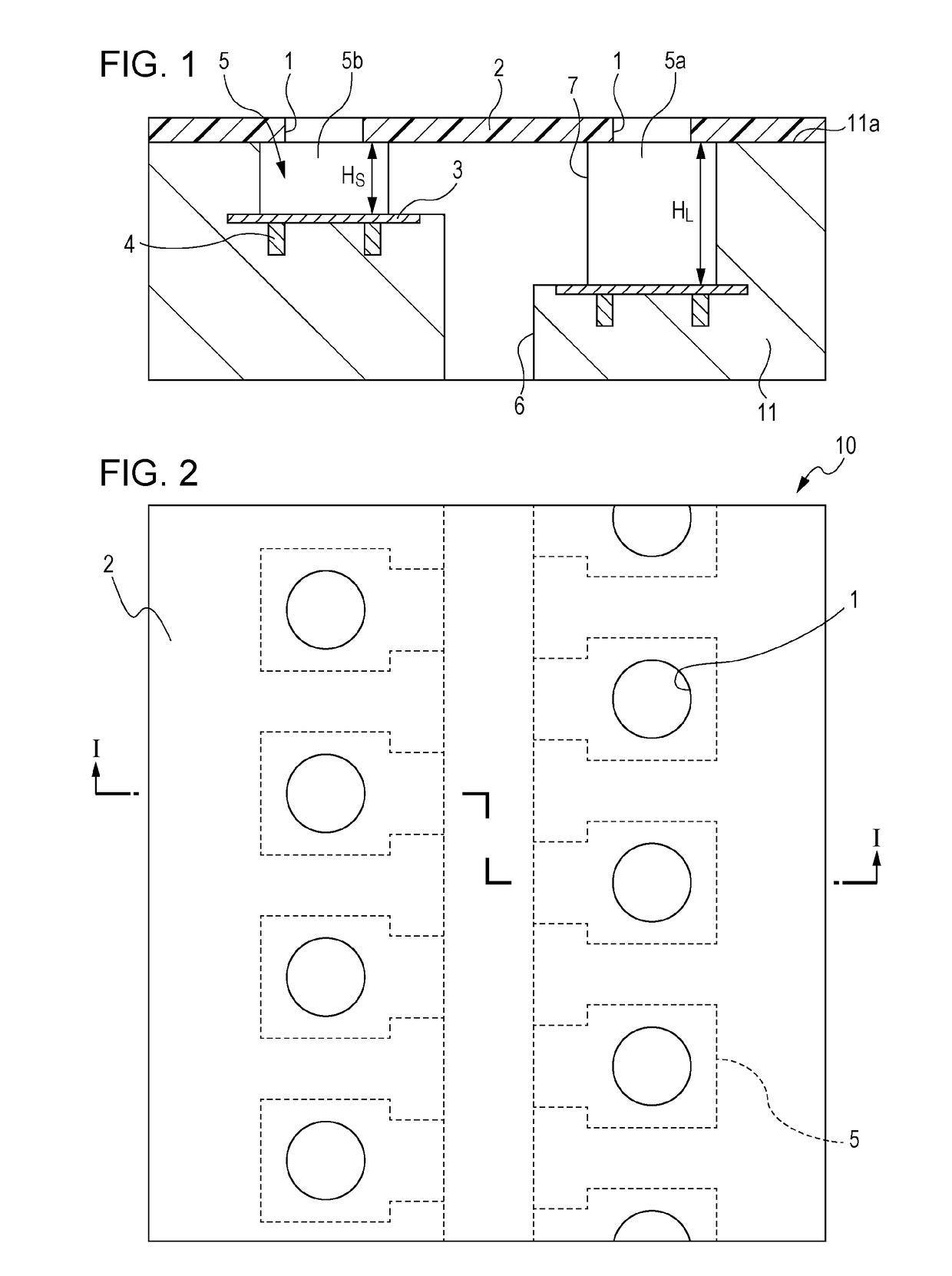
[0021]FIG. 2 is a plan view of a liquid discharge head 10 according to a first embodiment. A plurality of discharge ports 1 are formed in a discharge-port-forming member 2. A plurality of pressure chambers 5 are formed so as to be positioned further toward the back side as viewed in FIG. 2 than the discharge-port-forming member 2 in such a manner as to correspond to the discharge ports 1. FIG. 1 is a sectional view taken along line I-I of FIG. 2.

[0022]As illustrated in FIG. 1 and FIG. 2, the liquid discharge head 10 includes the discharge-port-forming member 2 that has the discharge ports 1 through which a liquid, such as an ink, is to be discharged and a substrate 11 that has a joint surface 11a, which is joined to the discharge-port-forming member 2. The discharge-port-forming member 2 is formed as a plate having a fixed thickness. In the first embodiment, the substrate 11 is a pressure-chamber-forming member, and the pressure chambers 5 (5a and 5b) each of which is in communicati...

second embodiment

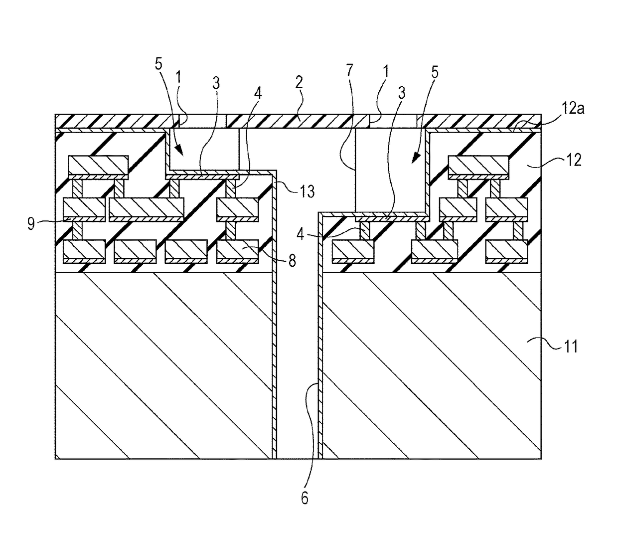
[0025]FIG. 3 is an enlarged sectional view taken along line I-I of FIG. 2 and is a diagram illustrating a liquid discharge head according to a second embodiment that includes a plurality of wiring layers 8 connected to the electrodes 4.

[0026]In the second embodiment, the differences from the first embodiment are that a pressure-chamber-forming member is an insulating film 12 that is formed on the substrate 11, and that the plurality of pressure chambers 5 are formed by recessing a flat top surface of the insulating film 12, which is a joint surface 12a joined to the discharge-port-forming member 2, in a film-thickness direction. Referring to FIG. 3, the plurality of wiring layers 8 are formed in such a manner as to be included in the insulating film 12 is formed on the substrate 11 that is formed of a silicon substrate. The plurality of wiring layers 8 are formed at different positions in a depth direction of the pressure chambers 5, which is a direction from the joint surface 12a t...

third embodiment

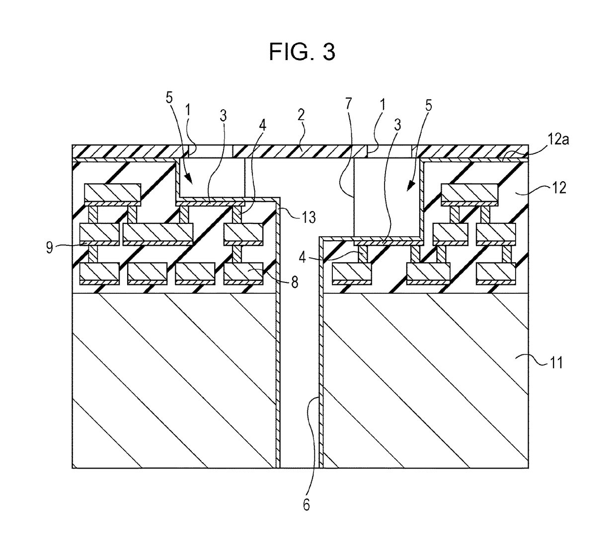
[0036]FIGS. 5A to 5E are sectional views illustrating steps of a method for manufacturing the liquid discharge head 10 according to the present invention. Although FIGS. 5A to 5E illustrate the method for manufacturing the liquid discharge head 10 that has the configuration illustrated in FIG. 3, the present invention can also be applied to the configurations illustrated in FIG. 1 and FIG. 4. Each step of the manufacturing method will be described in detail below.

[0037]The step illustrated in FIG. 5A is a step of preparing the substrate 11 that has a main surface 11b on which the insulating film 12 is formed. The plurality of wiring layers 8 and barrier metals 9 are included in the insulating film 12. From the standpoint of processability and productivity, a silicon oxide film may be used as the insulating film 12 and can be deposited by plasma enhanced chemical vapor deposition (PECVD). A material, such as Al, AlCu, AlSi, and AlSiCu, can be used as a wiring metal that forms each of...


PUM


Abstract

A method for manufacturing a liquid discharge head that includes a discharge-port-forming member, which has discharge ports through which a liquid is discharged, and a pressure-chamber-forming member, which includes pressure chambers communicating with the discharge ports and each including a heating resistor formed in a bottom portion thereof and which has a surface joined to the discharge-port-forming member, includes preparing the pressure-chamber-forming member in which wiring layers each including a barrier metal as a base member are formed, forming the pressure chambers, whose depths from the surface are different from each other and which include the heating resistors each formed of one of the barrier metals, by recessing the pressure-chamber-forming member from the surface and removing at least two of the wiring layers, which are formed at different positions in a depth direction from the surface, to expose the corresponding barrier metals, and forming the discharge-port-forming member on the surface.

Description

BACKGROUND OF THE INVENTION[0001]Field of the Invention[0002]The present invention relates to a liquid discharge head that discharges a liquid droplet and a method for manufacturing the liquid discharge head.[0003]Description of the Related Art[0004]As an example of a configuration of a liquid discharge head, a configuration disclosed in Japanese Patent Laid-Open No. 2003-311964 (hereinafter referred to as Patent Document 1) in which at least two or more discharge portions, each of which is capable of discharging a liquid droplet having a size different from that of the liquid droplet discharged by the other discharge portion, are disposed in one chip is known. With this configuration, a liquid discharge head that is capable of discharging liquid droplets having a plurality of sizes from a single chip by changing the substantial volume of a liquid, which is applied with pressure generated when part of the liquid bubbles, may be obtained. In particular, in the invention disclosed in ...

Claims


Application Information

Patent Timeline
Patent Type & Authority Patents(United States)
IPC IPC(8): B41J2/14B41J2/16
CPCB41J2/14088B41J2/1404B41J2/14016B41J2/14129B41J2/1603B41J2/1628B41J2/1629B41J2/1631B41J2/1642B41J2/1646B41J2202/11B41J2202/13B41J2202/18
Inventor UYAMA, MASAYASAKURAI, MAKOTOTERUI, MAKOTO
Owner CANON KK
Why Eureka
Try Eureka