Ejector cycle system

Inactive Publication Date: 2004-06-03
DENSO CORP
View PDF7 Cites 67 Cited by
  • Summary
  • Abstract
  • Description
  • Claims
  • Application Information

AI Technical Summary

Problems solved by technology

Therefore, in the ejector cycle system, it is difficult to perform heating operation by using a hot gas heater cycle through which high-pressure

Method used


Image

  • Ejector cycle system
  • Ejector cycle system
  • Ejector cycle system

Examples


Example

First Embodiment

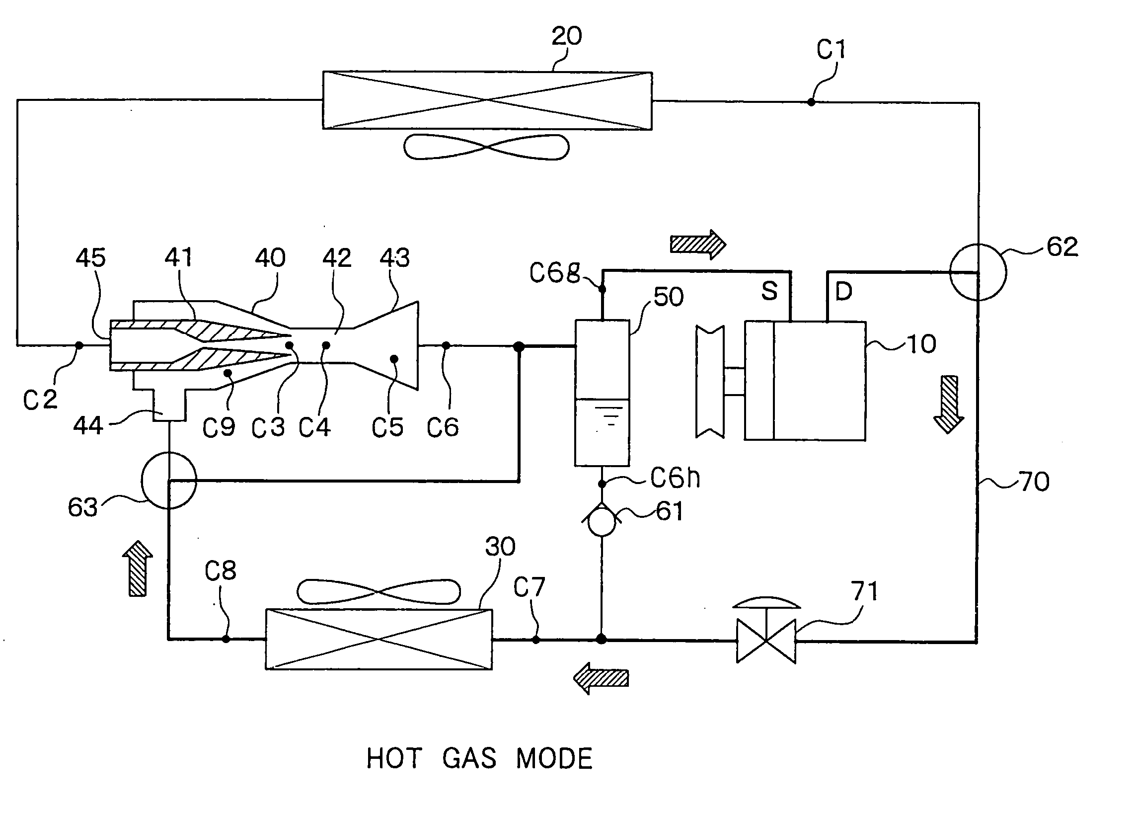
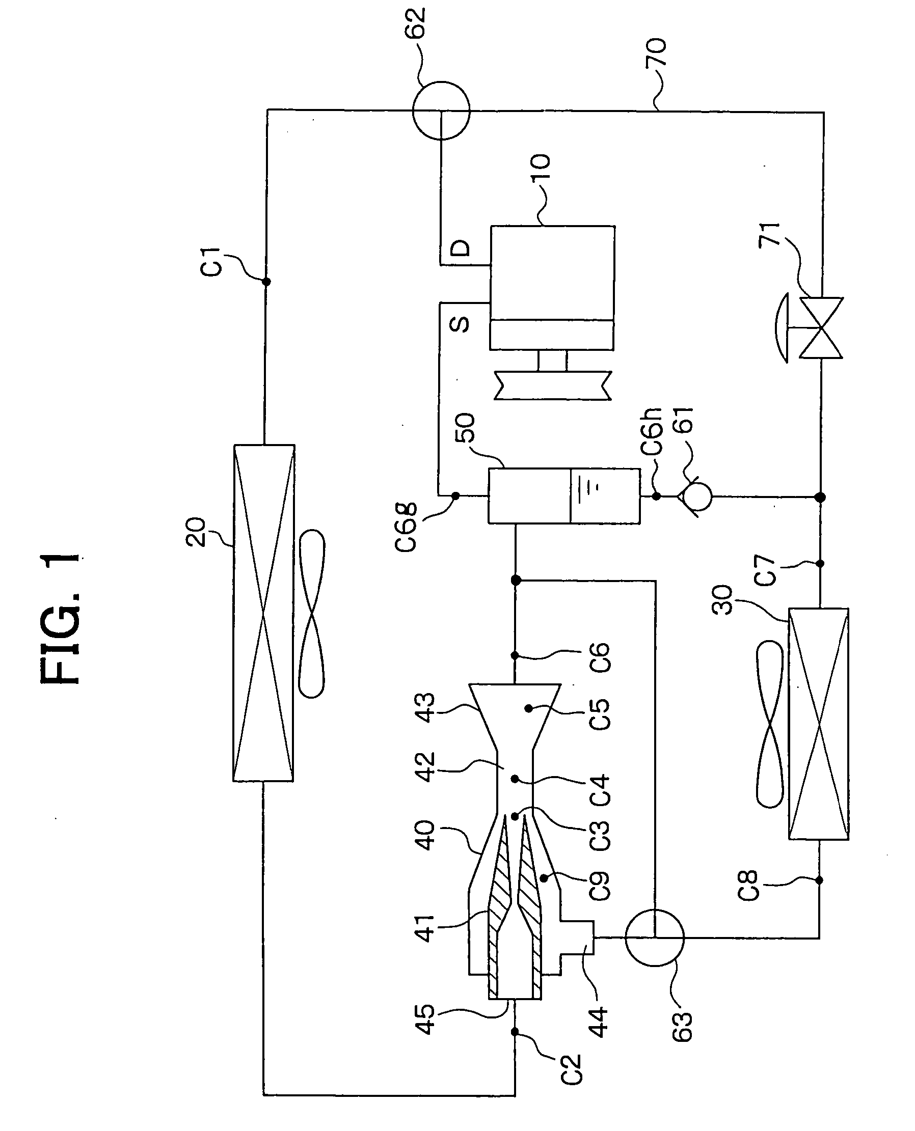
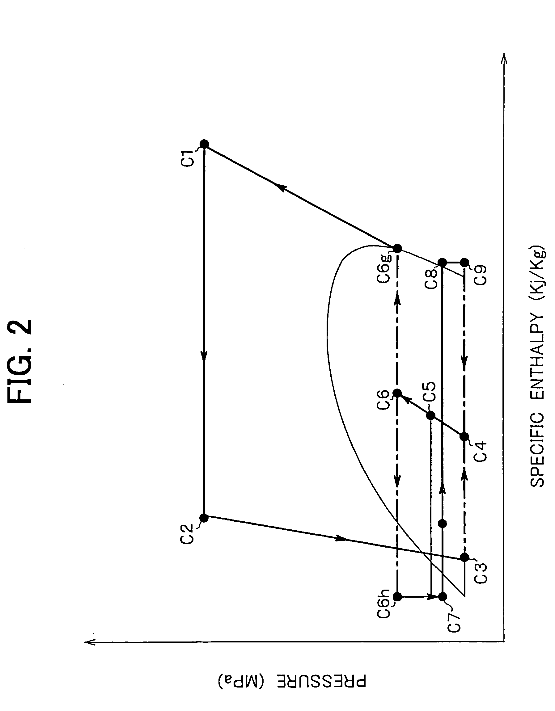
[0024] The first embodiment will be described with reference to FIGS. 1-5. In the first embodiment, an ejector cycle system of the present invention is typically used for a vehicle air conditioner.

[0025] In the ejector cycle system of FIG. 1, a compressor 10 for sucking and compressing refrigerant is a continuously variable displacement compressor that is operated by motive power from a vehicle engine for running a vehicle, for example. However, the compressor 10 may be a fixed displacement compressor that is driven by an electric motor. An amount of refrigerant discharged from the compressor 10 is controlled so that air-conditioning capacity required in an interior heat exchanger 30 is controlled. Specifically, a cooling capacity required in a cooling mode and a heating capacity required in a hot gas heating mode can be controlled by controlling the amount of refrigerant discharged from the compressor 10.

[0026] An exterior heat exchanger 20 performs heat-exchange be...

Example

Second Embodiment

[0039] In the above-described first embodiment, the refrigerant flow is switched by the first and second three-way valves 62, 63. However, in the second embodiment, as shown FIG. 6, the refrigerant flow is switched by two-way valves 62a, 62b, 63a. Specifically, in the cooling mode, the valve 62a is opened, the valve 62b is closed, and the valve 63a is closed. On the other hand, in the hot gas heating mode, the valve 62a is closed, the valve 62b is opened, and the valve 63a is opened. Therefore, in the hot gas heating mode, hot gas refrigerant discharged from the compressor 10 flows into the interior heat exchanger 30 through the bypass passage 70. In this case, refrigerant from the interior heat exchanger 30 flows into the gas-liquid separator 50 while bypassing at least the nozzle 41 of the ejector 40. That is, refrigerant flowing from the interior heat exchanger 30 can be introduced into the pressurization portion (i.e., the mixing portion 42 and the diffuser 43)....

Example

Third Embodiment

[0041] In the above-described first embodiment, refrigerant flowing out of the interior heat exchanger 30 is introduced to the gas-liquid separator 50 while bypassing the ejector 40 in the hot gas heating mode. However, in the third embodiment, as shown in FIG. 7, refrigerant flowing out of the interior heat exchanger 30 is introduced to the gas-liquid separator 50 through the ejector 40 in the hot gas heating mode. In the example of FIG. 7, the refrigerant flowing out of the interior heat exchanger 30 is introduced to both of the low-pressure refrigerant suction port 44 of the ejector 40 and the refrigerant inlet port 45 of the nozzle 41. However, the refrigerant flowing out of the interior heat exchanger 30 can be introduced to one of the low-pressure refrigerant suction port 44 and the refrigerant inlet port 45 in the hot gas heating mode. For example, all refrigerant from the interior heat exchanger 30 can be introduced to the refrigerant inlet port 45 of the noz...


PUM


Abstract

In a hot gas heating mode of an ejector cycle system, hot gas refrigerant discharged from a compressor is introduced to an interior heat exchanger while bypassing an exterior heat exchanger. The refrigerant discharged from the interior heat exchanger can flow into an ejector from at least an inlet of a nozzle of the ejector, and flows into the gas-liquid separator, in the heating mode. Alternatively, refrigerant discharged from the compressor can be supplied to the interior heat exchanger through a clearance between an outer wall of the nozzle and an inner wall of a nozzle housing portion, while bypassing the exterior heat exchanger in the heating mode. Here, the nozzle is disposed in the nozzle housing portion, and a part of pressurizing portion is defined by the nozzle housing portion. Thus, the heating mode can be readily performed in the ejector cycle system.

Description

[0001] This application is related to and claims priority from Japanese Patent Application No. 2002-345341 filed on Nov. 28, 2002, the content of which is hereby incorporated by reference.[0002] 1. Field of the Invention[0003] The present invention relates to an ejector cycle system that can set one of a cooling mode and a hot gas heating mode in an interior heat exchanger. The ejector cycle system is effectively used for a vehicle air conditioner.[0004] 2. Description of Related Art[0005] Generally, a vapor compression refrigerant cycle includes an ejector cycle system and an expansion valve cycle system. For example, in an ejector cycle system disclosed in JP-A-5-149652, refrigerant evaporated in an evaporator is sucked into an ejector while refrigerant is decompressed and expanded in the ejector, and pressure of refrigerant to be sucked into a compressor is increased by converting expansion energy to pressure energy. On the other hand, in an expansion valve cycle system disclosed...

Claims


Application Information

Patent Timeline
IPC IPC(8): B60H1/00F04F5/04F25B9/00F25B41/00F25B41/04F25B1/00
CPCB60H1/00899B60H2001/3298F04F5/04F25B9/008F25B41/00F25B41/04F25B2700/21163F25B2341/0012F25B2341/0013F25B2341/0014F25B2400/0403F25B2400/0407F25B2700/1931F25B2309/061F25B41/20F25B41/24
Inventor YAMAGUCHI, MOTOHIROOHTA, HIROMISATO, YUKIMASA
Owner DENSO CORP
Why Eureka
Try Eureka