Link actuating device

a technology of actuating device and link, which is applied in the direction of manipulators, joints, program-controlled manipulators, etc., can solve the problems of increasing the size of increasing the size of the device, and increasing the rigidity of the mechanism as a whole, so as to improve the workability and assembly properties of the components.

Active Publication Date: 2005-09-15
NTN CORP
View PDF16 Cites 68 Cited by
  • Summary
  • Abstract
  • Description
  • Claims
  • Application Information

AI Technical Summary

Benefits of technology

[0036] As described above, in the link actuating device of the present invention, of the components of the link mechanism including the input and output members and the end link member or the intermediate link membe

Problems solved by technology

However, in the above-described parallel link mechanism, the operation angle of each link is rather small, so that an attempt to set the operation range for the traveling plate large results in a rather large link length, which leads to an increase in the size of the mechanism as a whole, resulting in an increase in the device size.
Further, the rigidity of the mechanism as a whole is rather low, so that there is a limitation regarding the weight of the tool that can be mounted on the traveling plate, that is, the weight capacity of the traveling plate.
Therefore, the rigidity of the link mechanisms is rather low.
However, in a bearing detachment prevention structure for the rotation pair portions of a link mechanism utilizing a snap

Method used


Image

  • Link actuating device
  • Link actuating device
  • Link actuating device

Examples


Embodiment Construction

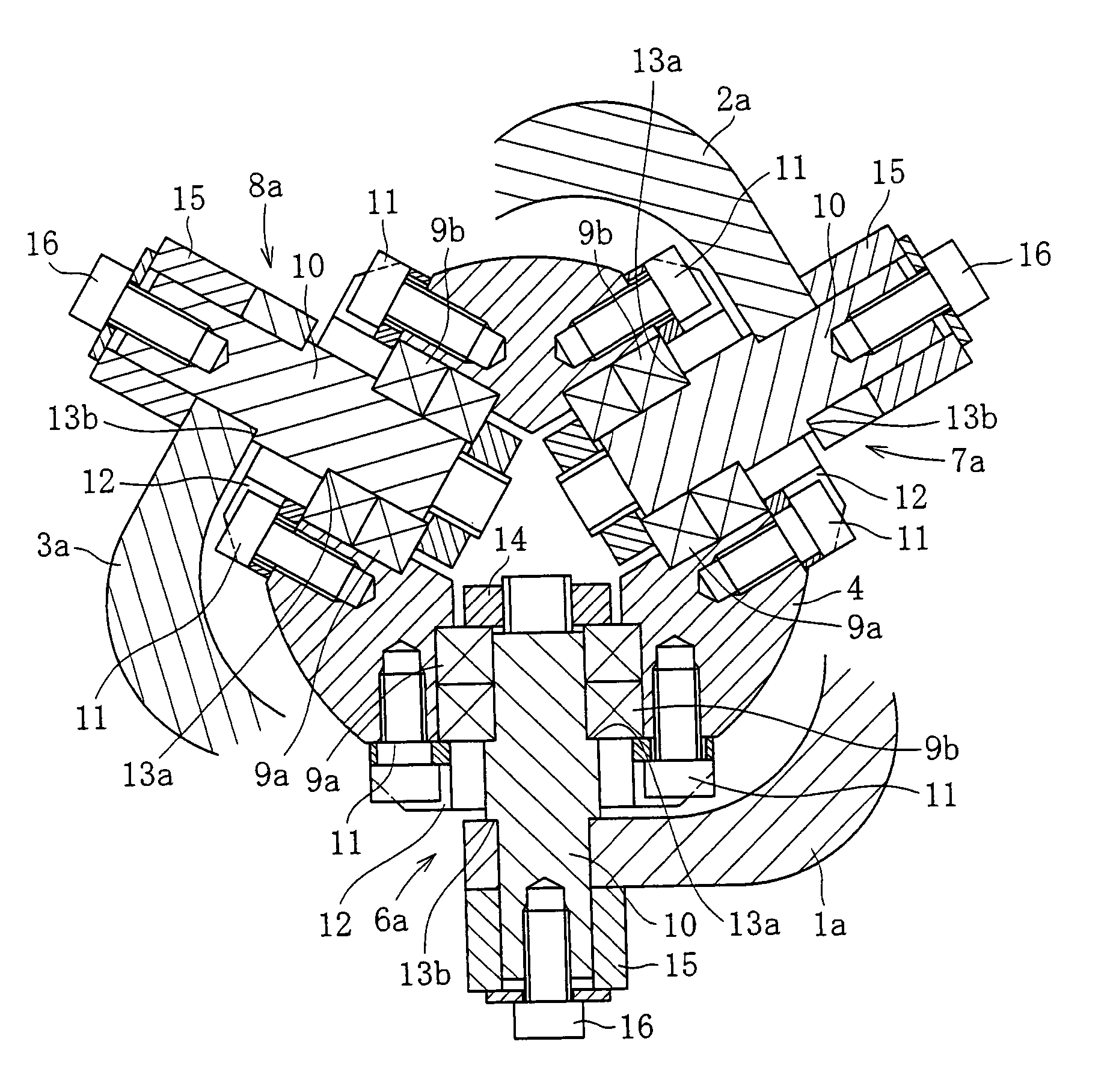
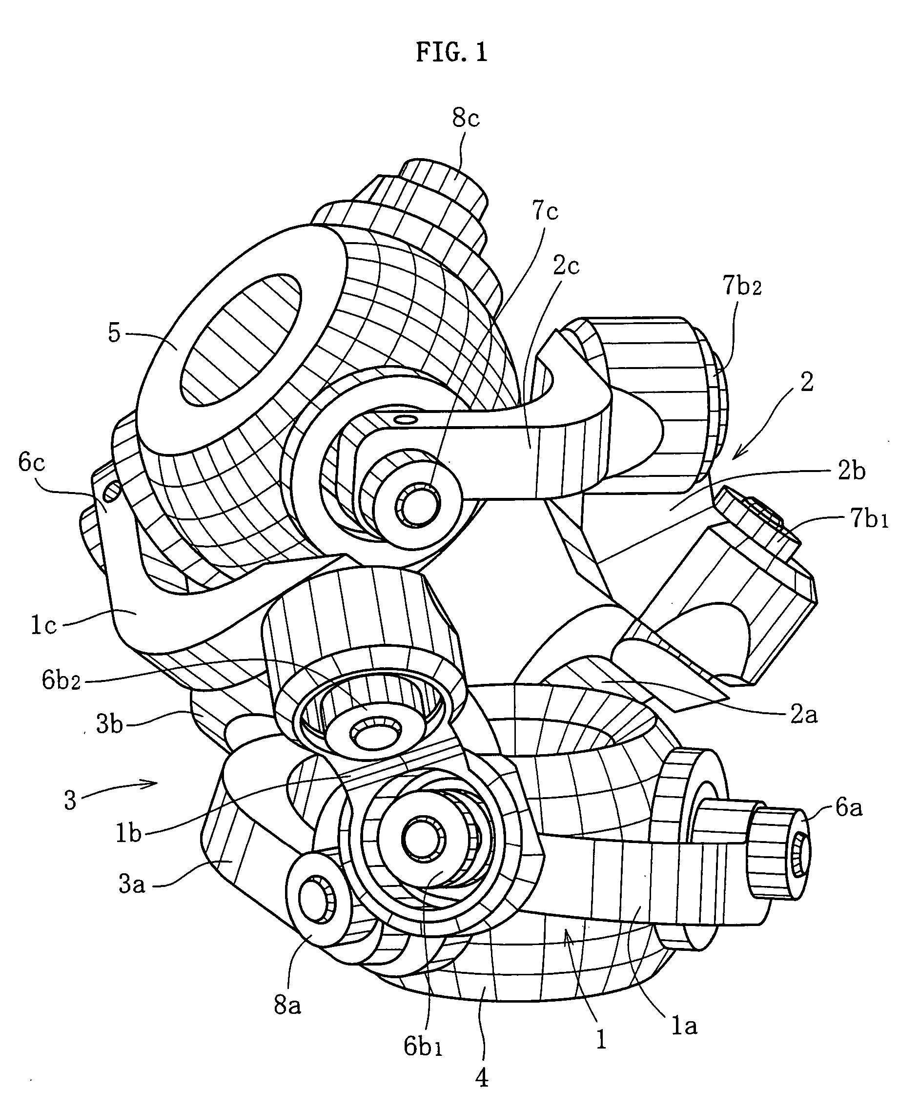
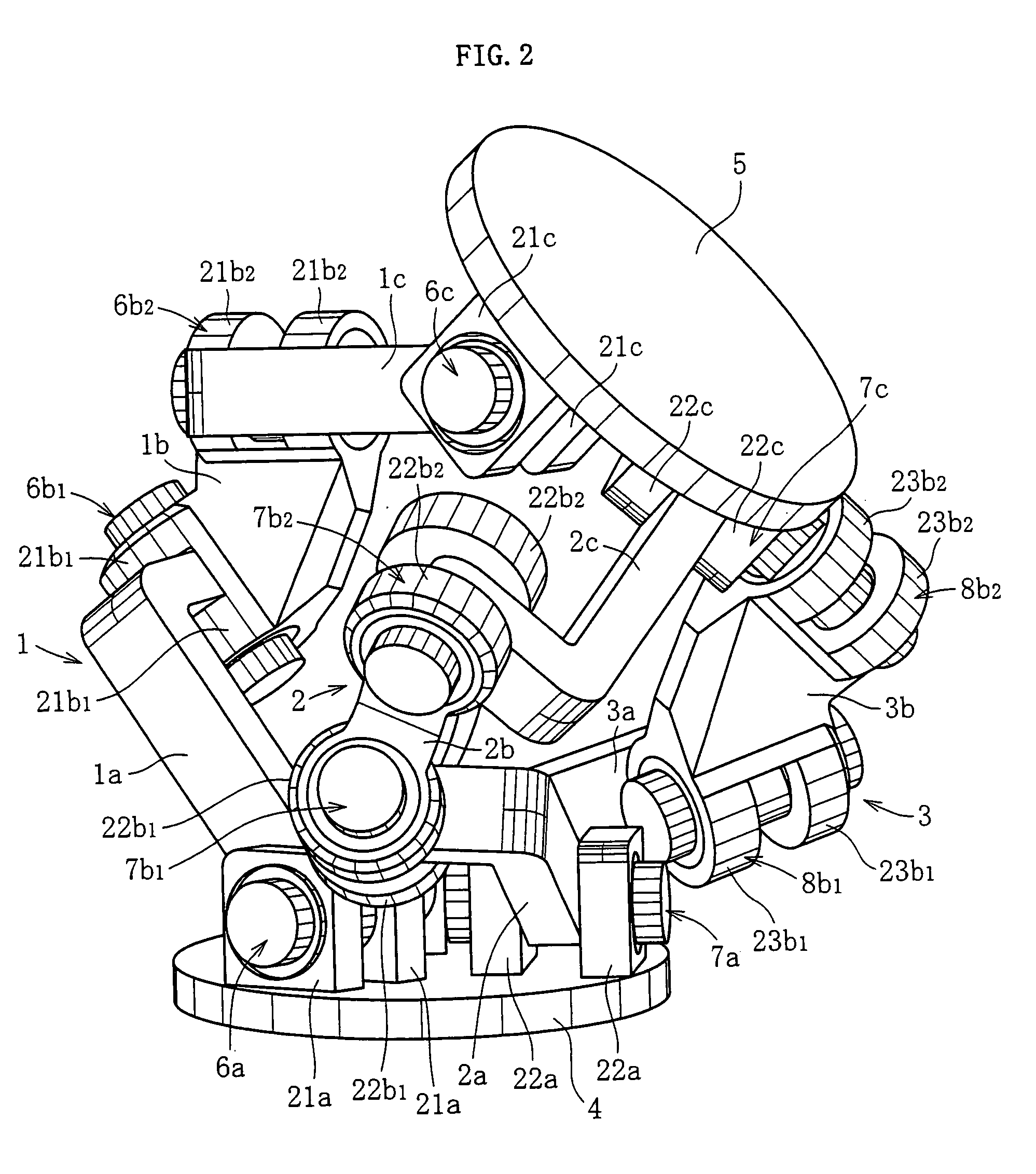
[0068] A link actuating device of an embodiment shown in FIGS. 1 and 2 is equipped with three sets of link mechanisms 1 through 3 to be utilized, for example, in link mechanisms, such as robot joints, for quickly and accurately executing an operation, such as a complicated machining or article handling in a three-dimensional space. The three sets of link mechanisms 1 through 3 are of the same geometrical configuration.

[0069] The link mechanisms 1 through 3 of the embodiment shown in FIG. 1 are of the rotation symmetry type. The positional relationship between an input member 4 and input side end link members 1a through 3a, and the positional relationship between an output member 5 and output side end link members 1c through 3c, are in rotation symmetry with each other with respect to the center lines of intermediate link members 1b through 3b.

[0070] As shown in FIGS. 1 and 2, the link mechanisms 1 through 3 are respectively composed of the input side end link members la through 3a...


PUM


Abstract

In a bearing detachment prevention structure provided in a rotation pair portion of a link mechanism, play filling-up and pre-load adjustment for the bearing are realized with ease. As a means for therefor, there is provided a link actuating device having three or more sets of link mechanisms in each of which end link members are rotatably connected to input and output members respectively arranged on the input and output sides, the respective end link members on the input and output sides being rotatably connected to intermediate link members to form four rotation pair portions, the input and output sides being geometrically the same with respect to a cross section in a central portion of each link mechanism, in which each rotation pair portion of the link mechanisms has a bearing structure consisting of two bearings, with a play filling-up means for regulating axial movement of the two bearings being provided in the rotation pair portions. Further, by appropriately determining the configuration of each component forming the link mechanisms, interference between the components during operation of the link mechanisms is prevented. As a means therefor, a beveled portion is formed on the link side peripheral end edge portion of each input member, whereby interference between the end link member and the outer peripheral surface of the rotation pair portion of each intermediate link member is prevented.

Description

BACKGROUND OF THE INVENTION [0001] The present invention relates to a link actuating device to be utilized in a link mechanism, such as a robot joint, for quickly and accurately executing an operation in a three-dimensional space, such as a complicated machining or article handling. [0002] For example, as a link actuating device for quickly and accurately executing an operation in a three-dimensional space, such as a complicated machining or article handling, there exists an operation device equipped with a parallel link mechanism (see, for example, JP 2000-94245 A). [0003] This operating device is equipped with a parallel link mechanism in which a plurality of links connecting a base plate and a traveling plate are caused to expand and contract in cooperation with each other, thereby varying the position and attitude of the traveling plate with respect to the base plate. By mounting a tool to the traveling plate of this parallel link mechanism and rotatably arranging a table retain...

Claims


Application Information

Patent Timeline
IPC IPC(8): B25J17/00
CPCY10T74/20329B25J9/0048
Inventor ISOBE, HIROSHISONE, KEISUKE
Owner NTN CORP
Why Eureka
Try Eureka