Ink jet printer

a jet printer and printer body technology, applied in printing and other directions, can solve the problems of increasing the time necessary for wiping, and achieve the effect of reducing the time necessary for wiping

Active Publication Date: 2019-10-29
ROLAND DG CORP
View PDF9 Cites 0 Cited by
  • Summary
  • Abstract
  • Description
  • Claims
  • Application Information

AI Technical Summary

Benefits of technology

[0007]Preferred embodiments of the present invention provide ink jet printers each including a wiper that efficiently wipes nozzle surfaces of ink heads in a staggered pattern.
[0009]In an ink jet printer according to a preferred embodiment of the present invention, the first ink head and the third ink head are disposed at the same position in the first direction and the second ink head and the fourth ink head are disposed at the same position in the first direction, but the first ink head and the third ink head are shifted from the second ink head and the fourth ink head in the first direction. In this example, the ink jet printer includes the first wiper to wipe the first nozzle surface and the third nozzle surface and the second wiper to wipe the second nozzle surface and the fourth nozzle surface, and thus ensure wiping of the nozzle surfaces. In the case of providing a single wiper that is relatively long in the first direction enough to wipe the first nozzle surface through the fourth nozzle surface, the wiper needs to be immersed in the cleaning solution for every wiping of the nozzle surfaces, and the step of removing the cleaning solution is needed every wiping. Thus, as the number of ink heads increases, the time necessary to perform wiping increases. On the other hand, in the case of including the first wiper and the second wiper, since the first wiper and the second wiper pivot by the same angle, in supplying the cleaning solution to the first wiper, the cleaning solution is supplied to the second wiper at the same time. In removing the cleaning solution remaining on the first wiper, the cleaning solution remaining on the second wiper is removed at the same time. Thus, the time necessary for wiping is reduced, as compared to the case of including a single wiper.
[0010]According to preferred embodiments of the present invention, ink jet printers include wipers capable of efficiently wiping nozzle surfaces of ink heads arranged in a staggered pattern.

Problems solved by technology

Thus, as the number of ink heads increases, the time necessary to perform wiping increases.

Method used


Image

  • Ink jet printer
  • Ink jet printer
  • Ink jet printer

Examples


Embodiment Construction

[0027]Ink jet printers (hereinafter simply referred to as a “printer” or “printers”) according to preferred embodiments of the present invention will be described hereinafter with reference to the drawings. The preferred embodiments described here are, of course, not intended to particularly limit the present invention. Elements and features having the same functions are denoted by the same reference characters, and description for the same members and parts will not be repeated or will be simplified as appropriate.

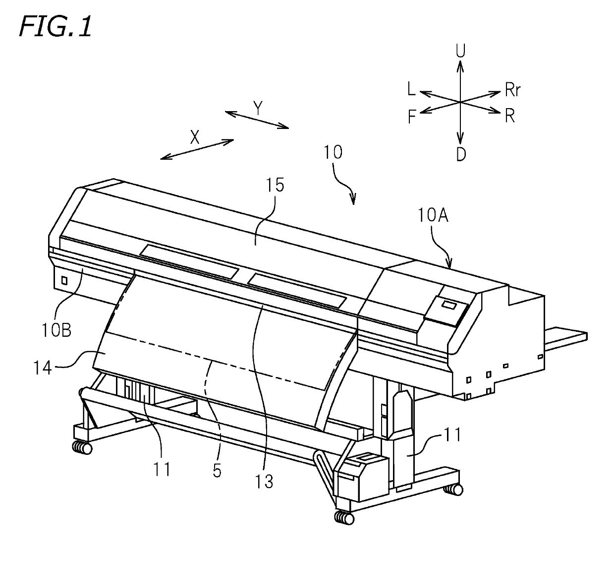
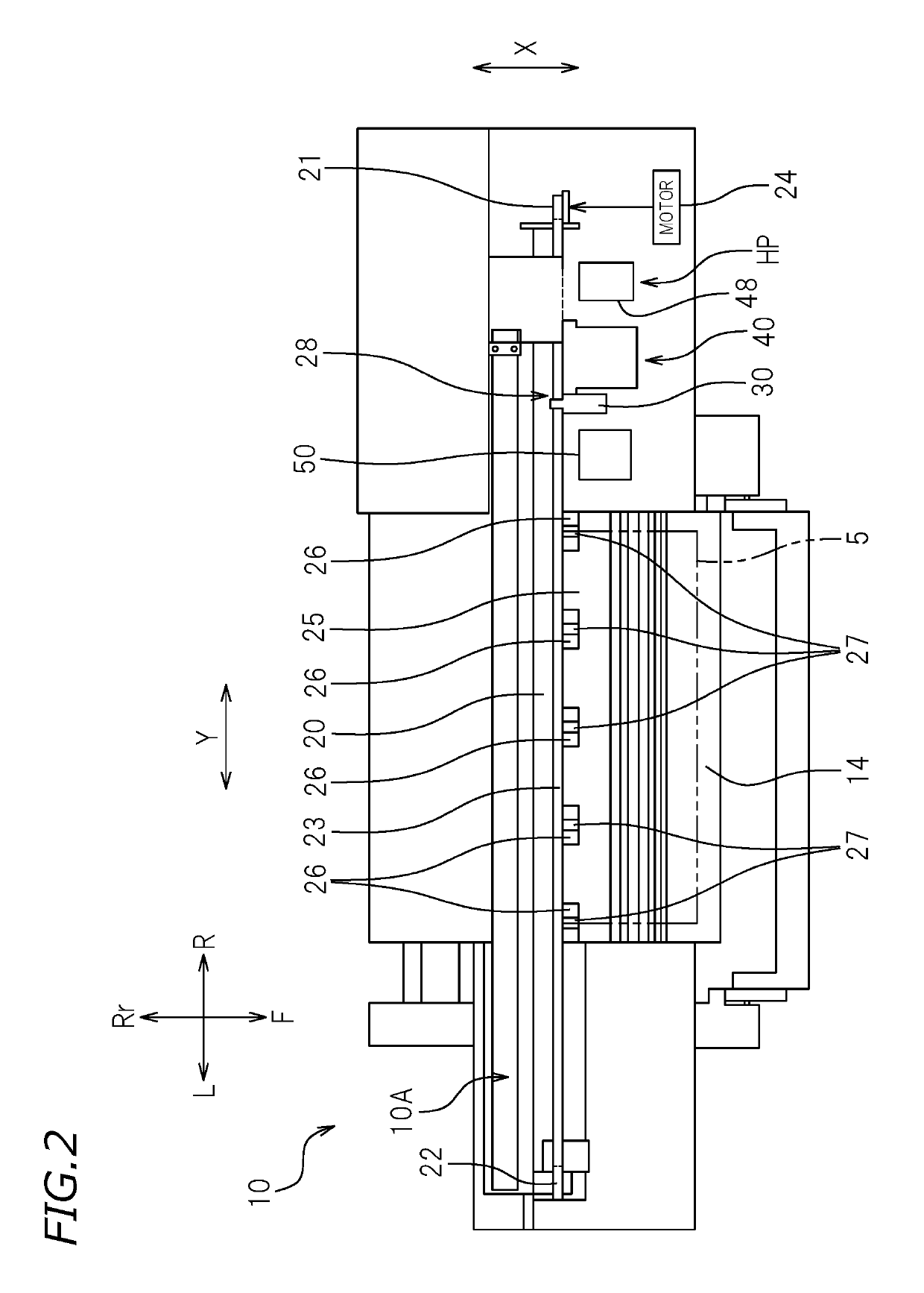
[0028]FIG. 1 is a perspective view of a printer 10 according to a preferred embodiment of the present invention. FIG. 2 is a plan view illustrating an internal configuration of the printer 10. As illustrated in FIG. 1, the printer 10 performs printing on a recording medium 5. The recording medium 5 is, for example, a recording sheet. The recording medium 5, however, is not limited to the recording sheet. The recording medium 5 is not limited to paper sheets such as plain ...


PUM


Abstract

A printer includes a first ink head including first nozzles arranged in a sub-scanning direction and a first nozzle surface on which the first nozzles are disposed, a second ink head disposed at a side of the first ink head in a main scanning direction and including second nozzles arranged in the sub-scanning direction and disposed partially at a position identical to a position of a portion of the first nozzles in the sub-scanning direction and a second nozzle surface on which the second nozzles are disposed, a first wiper that wipes the first nozzle surface at a first wiping position, and a second wiper that wipes the second nozzle surface at a second wiping position.

Description

CROSS REFERENCE TO RELATED APPLICATIONS[0001]This application claims the benefit of priority to Japanese Patent Application No. 2017-145677 filed on Jul. 27, 2017. The entire contents of this application are hereby incorporated herein by reference.BACKGROUND OF THE INVENTION1. Field of the Invention[0002]The present invention relates to an ink jet printer.2. Description of the Related Art[0003]An ink jet printer known to date includes an ink head including a plurality of nozzles and a nozzle surface on which the nozzles are formed, and performs predetermined printing on a recording medium via an ink jet process. The ink jet printer includes a maintenance mechanism for cleaning adherents such as ink and foreign matter adhering to portions near nozzles of the ink head.[0004]A known maintenance mechanism is, for example, a wiper for wiping a nozzle surface. When the wiper and the nozzle surface move relative to each other with the wiper being in contact with the nozzle surface, an adhe...

Claims


Application Information

Patent Timeline
Patent Type & Authority Patents(United States)
IPC IPC(8): B41J2/165
CPCB41J2/16552B41J2/16538B41J2/16541B41J2/16547
Inventor OKUNO, HIROSHIYAGI, HIDEKI
Owner ROLAND DG CORP
Why Eureka
Try Eureka