Internal gear pump

a gear pump and gear shaft technology, applied in the direction of machines/engines, rotary/oscillating piston pump components, liquid fuel engines, etc., can solve the problems of enlargement of the oil pump, loss of volumetric efficiency, and unusual noise and erosion of the pump

Inactive Publication Date: 2007-04-26
AISIN SEIKI KK
View PDF17 Cites 16 Cited by
  • Summary
  • Abstract
  • Description
  • Claims
  • Application Information

AI Technical Summary

Benefits of technology

[0008] According to an aspect of the present invention, an internal gear pump includes a housing forming a cylindrical space; a driven rotor having internal teeth and rotatably disposed in the cylindrical space; a driving rotor having external teeth engageable with the internal teeth and rotatably disposed in the driven rotor. The driving rotor and the driven rotor defines a plurality of interproximal spaces therebetween, the interproximal spaces repeatedly expanding and shrinking between the internal teeth of the driven rotor and the external teeth of the driving rotor engaged with the internal teeth so that fluid is suctioned and discharged. The internal gear pump further includes an inlet port formed at the housing in communication with the cy

Problems solved by technology

The occurrence of cavitation leads to various matters such as a loss of volumetric efficiency, unusual noise and erosion occurring within the pump.
However, in this structure, it is expected to surpass water hammering which occurs during discharging oil, ho

Method used


Image

  • Internal gear pump
  • Internal gear pump
  • Internal gear pump

Examples


Embodiment Construction

[0024] An embodiment of the present invention will be described below with reference to the attached drawings.

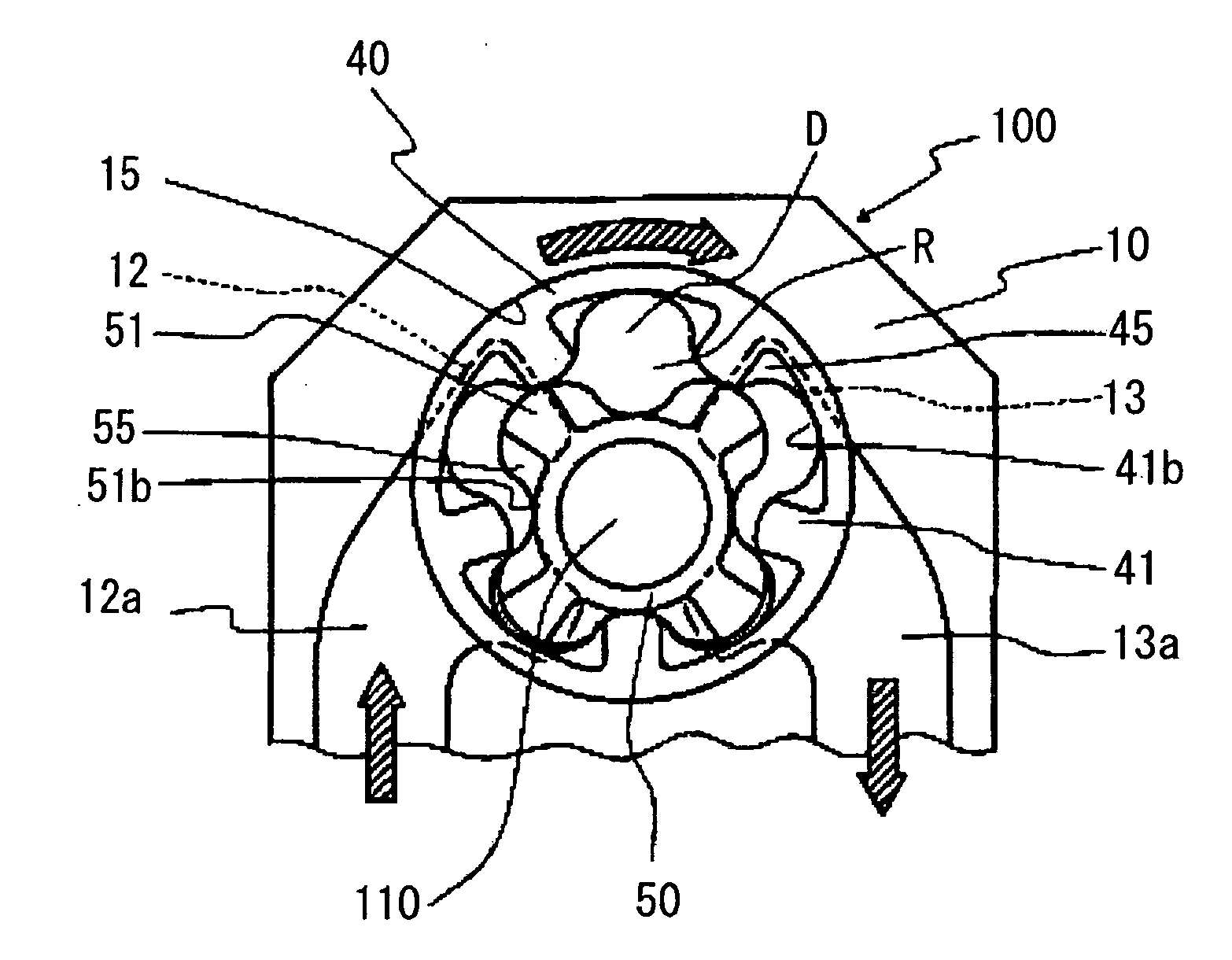
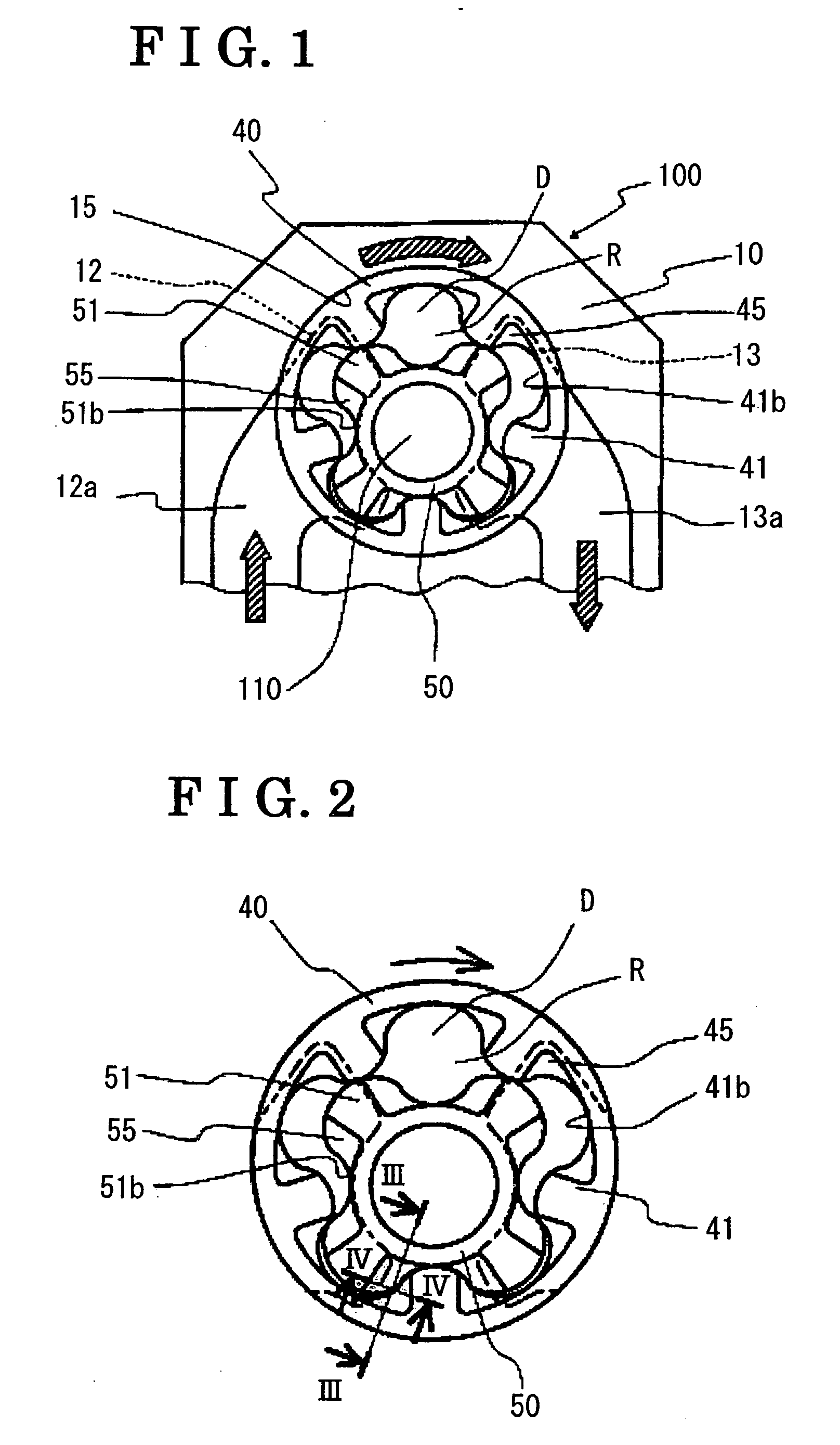
[0025]FIG. 1 is a back side view of a pump (internal gear pump) 100. The pump 100 includes; a body 10, a cover which is not illustrated, a driven rotor 40, a driving rotor 50, a shaft 110 which is rotatably fitted into the center of the driving rotor 50 to operate the driving rotor 50. A housing is constructed by the body 10 and the cover which is not illustrates and a rotor chamber 15, which is a cylindrical space, is defined in the housing, The driving rotor 50, into which the shaft 110 is rotatably fitted, and the driven rotor 40, which is engaged with the driving rotor 50 in an eccentric manner at a predetermined amount, are housed in the rotor chamber 15. The driving rotor 50 is provided with external teeth 51, while the driven rotor 40 is provided with internal teeth 41. The driving rotor 50 is engaged with the driven rotor 40 with the external teeth 51 meshed with th...


PUM


Abstract

An internal gear pump includes a recessed portion communicating with each corresponding interproximal space and defined in a way that the inlet port and the outlet port are prevented from communicating with each corresponding interproximal space at the position where each corresponding interproximal space attains the maximum volume. The recessed portion opens in a direction between a radial direction of the one of the driving rotor and the driven rotor and a circumferential direction thereof at each tooth of the one of the driving rotor and the driven rotor.

Description

CROSS REFERENCE TO RELATED APPLICATIONS [0001] This application is based on and claims priority under 35 U.S.C § 119 with respect to Japanese Patent Application 2005-305646, filed on Oct. 20, 2005, the entire content of which is incorporated herein by reference.FIELD OF THE INVENTION [0002] The present invention relates to an internal gear pump. More particularly, the present invention relates to an internal gear pump having a rotor structure, which prevents the occurrence of cavitations. BACKGROUND [0003] Generally, when known internal gear pumps, which are broadly employed in vehicle oil pumps, rotate at a high revolution and the intake flow rate is increased to exceed the pump suction rate due to resistance of viscosity, the pump induces cavitation within a suction passage (an inlet port and an interproximal space). The occurrence of cavitation leads to various matters such as a loss of volumetric efficiency, unusual noise and erosion occurring within the pump. [0004] One of the ...

Claims


Application Information

Patent Timeline
IPC IPC(8): F01C1/02F16N13/20F01C1/063
CPCF04C2/084F04C2/102F04C29/122
Inventor KUROKAWA, HIROYUKI
Owner AISIN SEIKI KK
Why Eureka
Try Eureka