
Drive device for ultrasonic linear motor

Inactive Publication Date: 2007-05-03
HONDA MOTOR CO LTD
View PDF5 Cites 7 Cited by
  • Summary
  • Abstract
  • Description
  • Claims
  • Application Information

AI Technical Summary

Benefits of technology

[0011] Because in this invention the driving parts are interposed between the rail and the base body like this, the driving forces produced by the driving parts act from the base body toward the side faces of the rail. Because the urging means urge the ultrasonic vibrators and the rollers toward the side faces of the rail, by adjusting the urging force it is possible to set the urging force on the rail to an optimal value, and an optimal driving torque can be obtained. Also, because the ultrasonic vibrators constituting the drive source are provided left-right symmetrically about the width-direction center of the base body, the driving force can be made strong stably, the base body can be driven with good left-right balance, and the base body can be moved strongly and smoothly.
[0012] In the drive device of the invention, preferably, an ultrasonic vibrator and rollers and urging means are received en bloc in a holding frame and fitted to the base body via this holding frame, and the rollers are removably mounted to the holding frame. When the rollers are provided removably on the holding frame like this, even when as a result of use in an environment such as a factory where a lot of foreign matter such as dust floats around the frequency of replacement of rollers becomes high due to wear and deterioration, the rollers can be replaced easily. As a result, the maintainability of the rollers can be increased.
[0013] The rail preferably has an upper face for bearing the load of the base body and sloping side faces formed on its left and right sides, the base body has opposing faces facing the sloping side faces, and the rail is gripped by rollers provided on the opposing faces and making contact with the sloping side faces and by the bottom face of the base body. Because the rollers are directed diagonally upward into contact with the sloping side faces by the urging means like this and the load of the base body is born by the top face side of the rail, the rail is gripped by the rollers and the bottom face of the base body. Consequently, looseness of the base body with respect to the rail in the up-down direction and the left-right direction is prevented from arising.
[0014] In addition, because most of the load of the base body is born by the top face of the rail, the load of the base body does not readily act on the ultrasonic vibrators of the driving parts. As a result, wear of the ultrasonic vibrators of the driving parts is greatly reduced and the durability of the ultrasonic vibrators increases.

Problems solved by technology

In particular, in an environment such as a factory where a lot of foreign matter such as dust floats around, there is the problem that with use over a long period wear proceeds quickly, and lifespan becomes short.

Method used


Image

  • Drive device for ultrasonic linear motor
  • Drive device for ultrasonic linear motor
  • Drive device for ultrasonic linear motor

Examples


first embodiment

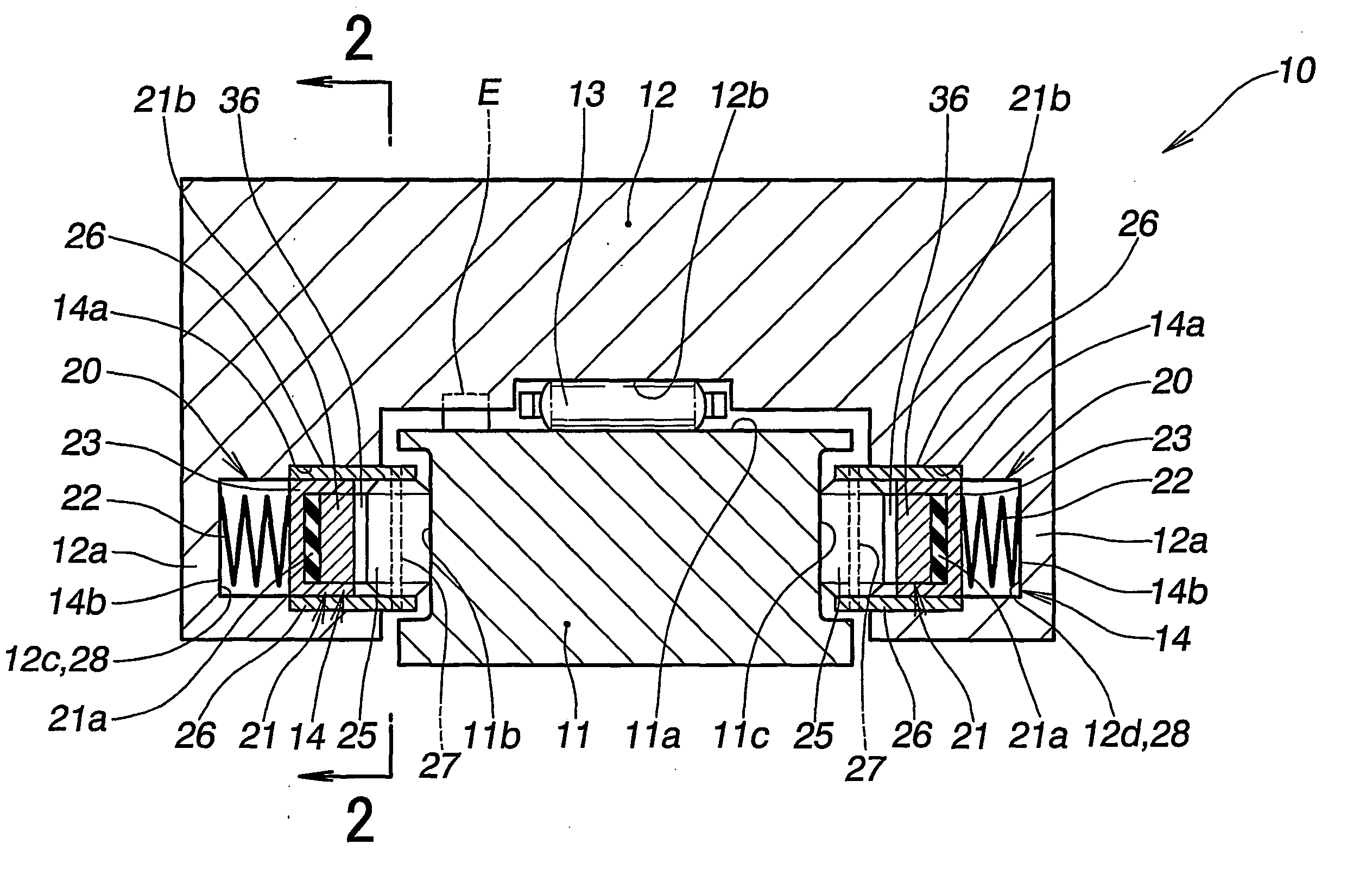
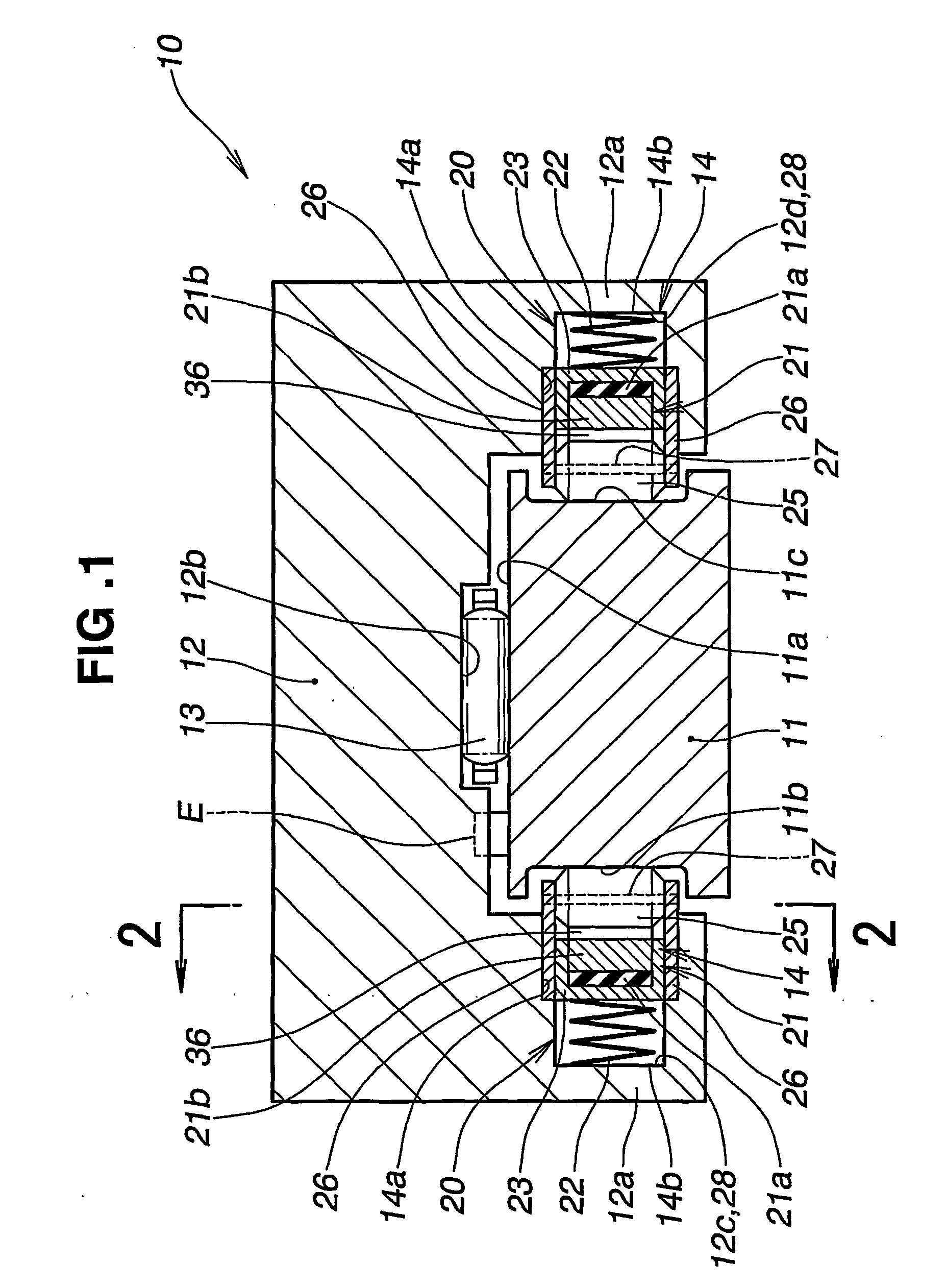
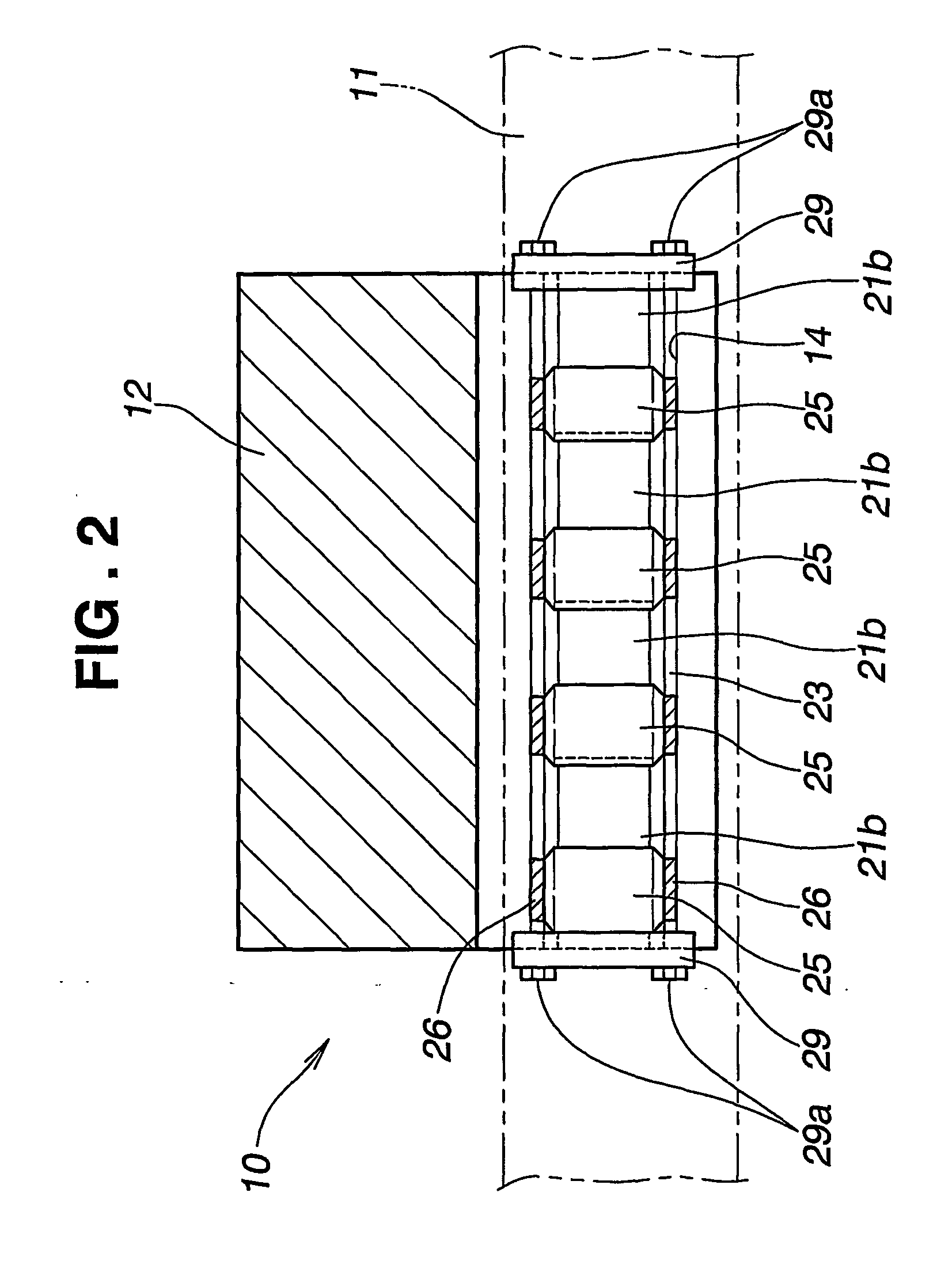
[0028] Although the ultrasonic linear motor drive device 10 of the first embodiment shown in FIG. 1 and FIG. 2 is an example wherein driving parts 20, 20 are provided on a base body 12 and the base body 12 is movable with respect to the rail 11, alternatively the base body 12 may be fixed and the rail 11 made movable with respect to the base body 12. That is, the rail 11 and the base body 12 may be constructed so as to be movable relative to each other.

[0029] The driving parts 20, 20 create driving forces for driving the base body 12. These driving parts 20, 20 are interposed between the left and right side faces 11b, 11c of the rail 11, which constitute guide faces, and the leg parts 12a, 12a of the base body 12. Each of the driving parts 20 has an ultrasonic vibrator 21, an urging member 22, and multiple rollers 25.

[0030] Each ultrasonic vibrator 21 is made up of a piezoelectric device 21a and a vibrating elastic member 21b, and produces a vibration and applies a turning force to...

second embodiment

[0055]FIG. 5 to FIG. 8 show a drive device of an ultrasonic linear motor according to a

[0056] Like the first embodiment, this linear motor is made up of a rail 42, a base body 44 and driving parts 50. The base body 44 is sectionally U-shaped with leg parts 44a, 44a at its sides. The leg parts 44a are formed so as to project outward and have holding hole parts 45 for holding the driving parts 50 in their inner side faces. Multiple bar-shaped bearings 46 are interposed between the top face 42a of the rail 42 and the bottom face 44b of the base body 44, and the base body 44 can move smoothly with respect to the rail 42. The side faces of the rail 42 have sectionally V-shaped guide grooves formed in them, and have left and right sloping side faces 42b, 42c of these guide grooves sloping downward. The driving parts 50, 50 are interposed between these sloping side faces 42b, 42c and opposing faces 44c, 44d (see FIG. 6) forming the holding hole parts 45 formed in the left and right leg par...


PUM


Abstract

This invention relates to a drive device of an ultrasonic linear motor having a rail (11, 42) and a base body (12, 44) and driving parts (20, 50) interposed between rail and base body. The base body is moved in a straight line with respect to the length direction of the rail by the driving parts. The driving parts are provided on left and right leg parts (12a, 44a) of the base body, and the load of the base body acts almost not at all on the driving part. The driving parts have ultrasonic vibrators (21,52) and rollers (25, 51) rotationally driven by the ultrasonic vibrators. The rollers are urged by urging means (22, 53) toward and into contact with guiding side faces (11b, 11c, 42b, 42c) of the rail, driving forces generated by the driving parts act on the guiding side faces of the rail, and the base body moves in the length direction of the rail.

Description

TECHNICAL FIELD [0001] This invention relates to a drive device of an ultrasonic linear motor in which with the vibration of ultrasonic vibrators as a drive source a rail and a base body move relatively with respect to a length direction. BACKGROUND ART [0002] An ultrasonic linear motor of this kind is made up of a base body having a piezoelectric device as a drive source in its center and having sliding parts at its ends, and a rail supporting the sliding parts of this base body. An ultrasonic linear motor in which the sliding parts of the base body are abutted with this rail and the base body moves relative to the rail is disclosed for example in JP-A-6-6989. The ultrasonic linear motor disclosed in this publication will be described on the basis of FIG. 10. [0003] The ultrasonic linear motor shown in FIG. 10 is made up of a rail 101, a base body 103 made of an elastic material and placed on the rail 101, piezoelectric devices 104, 104 mounted on the top of the base body 103 with ...

Claims


Application Information

Patent Timeline
IPC IPC(8): H02N2/00H01L41/09
CPCH02N2/026
Inventor ICHIKAWA, SHIGERUSUBE, YUUICHIMURAKAMI, EIJI
Owner HONDA MOTOR CO LTD
Learn More