

Method for detection and tracking of deformable objects using adaptive time-varying autoregressive model
- Summary
- Abstract
- Description
- Claims
- Application Information
AI Technical Summary
Benefits of technology
Problems solved by technology
Method used
Image


Examples
Embodiment Construction
General
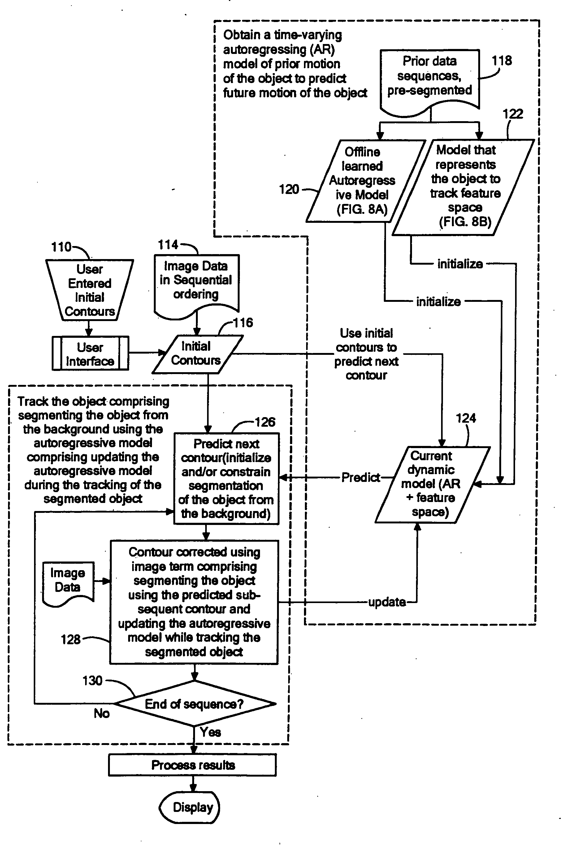
[0023] Referring now to FIG. 8 a flow diagram is shown for segmenting and tracking a moving object immersed in a background, here a background of noise, comprising: obtaining a time-varying autoregressive model of prior motion of the object to predict future motion of the object (described in more detail in Step 122A); and, tracking the object comprising segmenting the object from the background using the autoregressive model; and updating the autoregressive model during the tracking of the segmented object (described in more detail in Step 122B and Step 120A) below). More particularly, the method includes obtaining a time-varying autoregressive model of prior motion of the object to predict future motion of the object (Steps 120 and 122); predicting a subsequent contour of the object from the background using the obtaining time-varying autoregressive model comprising using the obtained time-varying autoregressive model to initialize and / or constrain segmentation of the obje...
PUM
 Abstract
Description
Claims
Application Information