Image forming apparatus

a technology of image forming apparatus and forming apparatus, which is applied in the direction of electrographic process apparatus, instruments, optics, etc., can solve the problems of insufficient heat fixing property of toner image, inability to perform, and long warm-up time, so as to prevent irregularities and secure the effect of toner

Inactive Publication Date: 2007-05-03
SHARP KK
View PDF14 Cites 15 Cited by
  • Summary
  • Abstract
  • Description
  • Claims
  • Application Information

AI Technical Summary

Benefits of technology

[0013] An object of the invention is to provide an image forming apparatus which performs both of a heat fixing operation and a wet fixing operation, the image forming apparatus in which a usage of fixer fluid is reduced so as to decrease a frequency of replenishing the fixer fluid, and which generates no irregularities of a toner image, fixing failure, and the like troubles attributable to a flow of excess fixer fluid and further shortens a warm-up time necessary for the heat fixing operation.

Problems solved by technology

In this image forming apparatus, fixing force of the toner image onto the recording material is enhanced, but there is a problem that it is not possible to perform a heat fixing operation until a temperature of a heating section rises up to a temperature (which will be hereinafter referred to as “a predetermined temperature” unless particularly mentioned) necessary for fusing the toner, so that a standby time lasting until reach of the predetermined temperature, namely a warm-up time will be required and in particular, when the image forming apparatus is activated, the warm-up time is longer than usual.
Further, even when the temperature of the heating section has reached the predetermined temperature, there is still a problem that a large amount of successive image formations results in delay of a heating operation conducted by the heating section, which is to be complied with the image formation, to therefore lead an insufficient heat fixing property of the toner image.
The image forming apparatuses of the heat fixing method have the above-mentioned problems in common.
However, in the image forming apparatus described in JP-A 2004-109747, the fixer fluid is used indispensably for softening the toner image and as a result, a usage of the fixer fluid is large.
This poses a problem that it is necessary to replenish a large amount of the fixer fluid frequently.
Although it is conceivable to enlarge a tank for storing the fixer fluid so as to eliminate necessity of the frequent replenishment of the fixer fluid, this leads to an increase in size of the image forming apparatus itself and is thus not preferable.
Further, in the image forming apparatus of JP-A 2004-109747, the evaporation of the excess liquid is promoted by the heating section, with the result that a problem originally posed in the heat fixing method such that the warm-up time is necessary, has not been solved.
In addition, a mutually-binding force of toner particles constituting the toner image is weak and therefore, a part of the toner may be swept away.
This may cause troubles such as irregularities of the toner image and thus irregularities of the image and fixing failure.

Method used


Image

  • Image forming apparatus
  • Image forming apparatus
  • Image forming apparatus

Examples


first embodiment

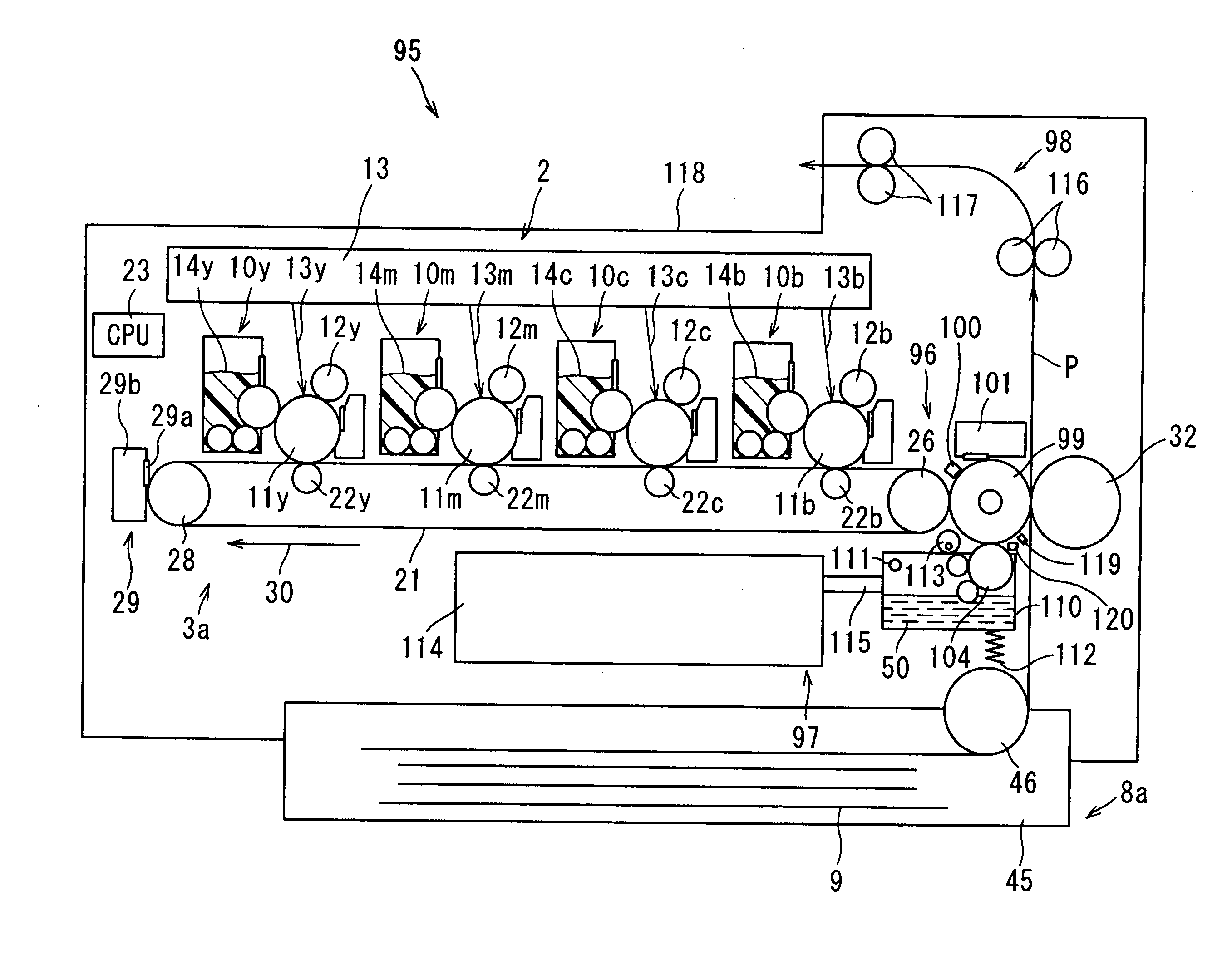
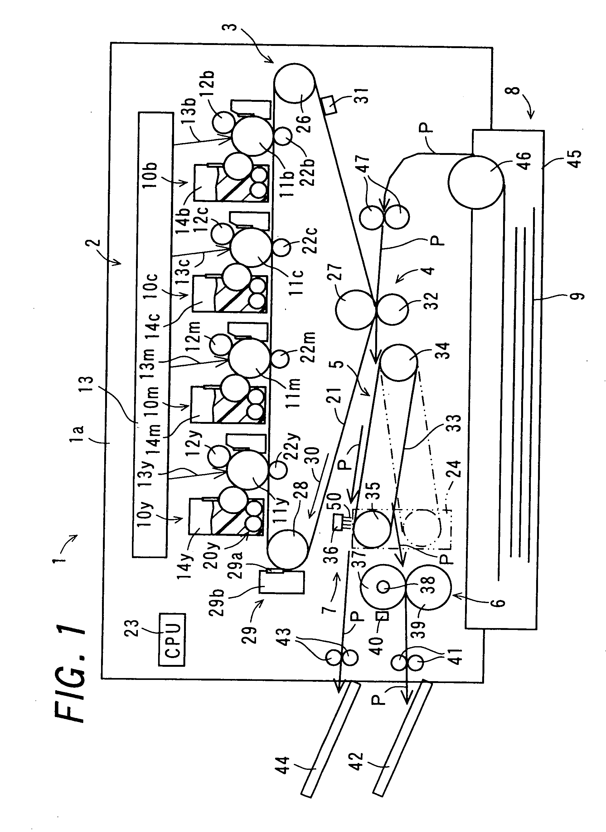
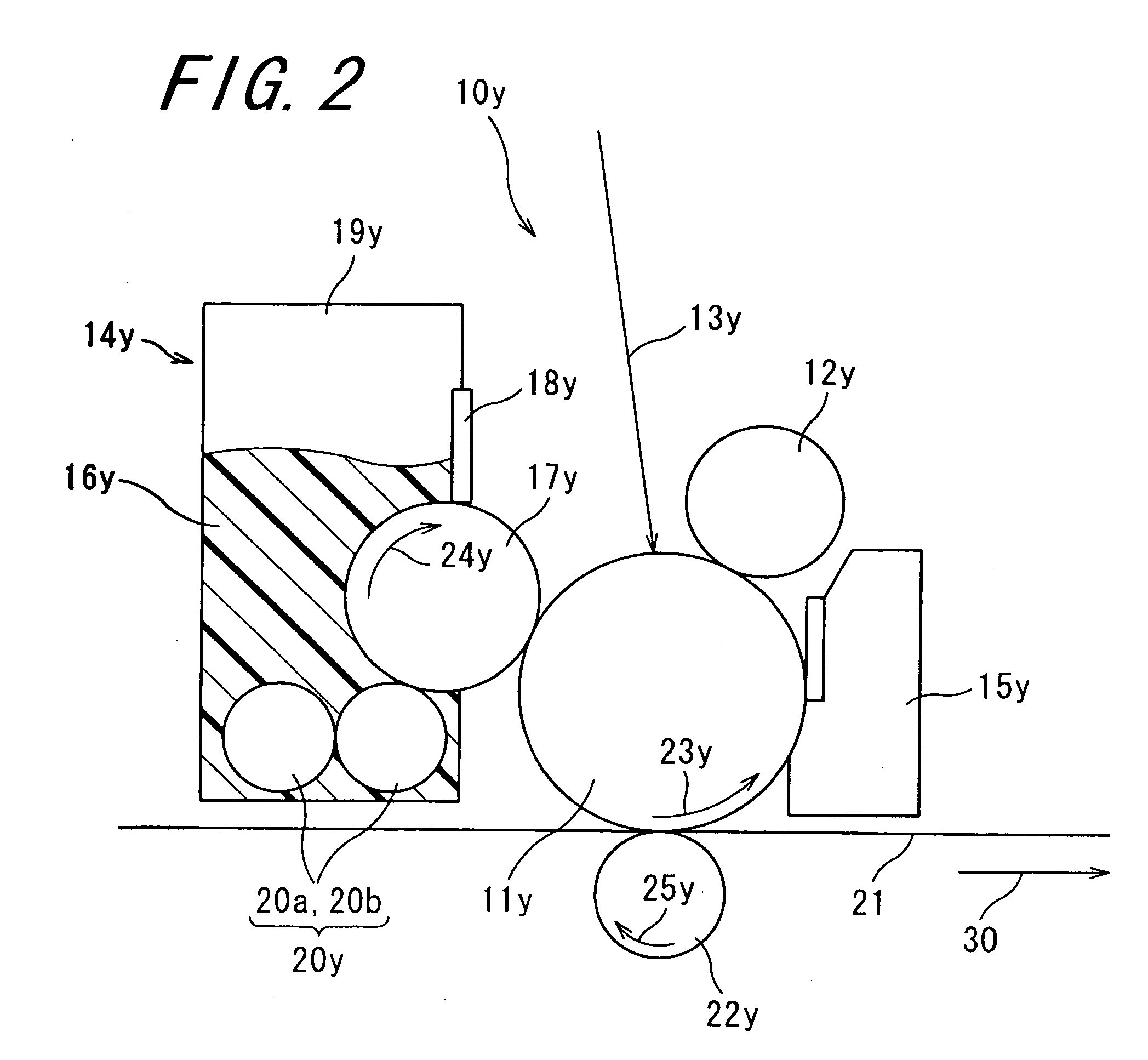
[0096]FIG. 1 is a sectional view schematically showing a constitution of an image forming apparatus 1 according to the invention. FIG. 2 is an enlarged sectional view showing a principal portion (a toner image forming section 2 which will be described later) of the image forming apparatus 1 depicted in FIG. 1. Note that the image forming apparatus 1 is a so-called tandem-configured image forming apparatus in which a transferring operation is conducted by sequentially superimposing toner images of four colors, i.e., yellow, magenta, cyan, and black one upon another.

[0097] The image forming apparatus 1 includes the toner image forming section 2, an image carrying section 3, a transferring section 4, a recording material conveying section 5, a wet fixing section 7, a heat fixing section 6, and a recording material supply section 8. In the embodiment, in order to define directions, the image forming apparatus 1 is provided so that an upper surface 1a thereof is parallel to an installati...

second embodiment

[0158]FIG. 4 is a sectional view schematically showing a constitution of an image forming apparatus 60 according to the invention. FIG. 5 is an enlarged sectional view showing a principal portion (a subsequently-explained wet fixing section 7a) of the image forming apparatus 60 depicted in FIG. 4. The image forming apparatus 60 is similar to the image forming apparatus 1. Therefore, the components that play the same or corresponding roles as in the image forming apparatus 1 will be denoted by the same reference numerals, and descriptions thereof will be omitted.

[0159] In the image forming apparatus 60, as features thereof, the fixer fluid 50 is applied to the surface of the fixing roller 37 by means of an applying roller 64 serving as an applying member, which is detachably provided on the surface of the fixing roller 37. And then, both of the heat fixing operation and the wet fixing operation are simultaneously performed on the unfixed toner image on the recording material 9 which ...

third embodiment

[0186]FIG. 6 is a sectional view schematically showing a constitution of an image forming apparatus 75 according to the invention. The image forming apparatus 75 is similar to the image forming apparatus 60. Therefore, the components that play the same or corresponding roles as in the image forming apparatus 60 will be denoted by the same reference numerals, and descriptions thereof will be omitted.

[0187] The image forming apparatus 75 is characterized in having a wet fixing section 7b instead of the wet fixing section 7a which includes the fixer fluid applying member 61 detachably provided on the surface of the fixing roller 37 in the heat fixing section 6 of the image forming apparatus 60. The wet fixing section 7b includes a fixer fluid applying member 76 detachably provided on the surface of the fixing roller 37. The image forming apparatus 75 has basically the same constitution as that in the image forming apparatus 60 other than the wet fixing section 7b.

[0188] The wet fixing...


PUM


Abstract

An image forming apparatus includes a toner image forming section, an image carrying section, a transferring section, a recording material conveying section, a heat fixing section, a wet fixing section, and a recording material supply section. In the image forming apparatus, a surface temperature of fixing roller in the heat fixing section is detected by a temperature sensor and according to a detected result, the recording material conveying section selects either one of the heat fixing section and the wet fixing section as a conveyance destination for a recording material carrying an unfixed toner image.

Description

CROSS-REFERENCE TO RELATED APPLICATION [0001] This application claims priority to Japanese Patent Application No. JP 2005-310264, which was filed on Oct. 25, 2005, the contents of which, are incorporated herein by reference, in their entirety. BACKGROUND OF THE INVENTION [0002] 1. Field of the Invention [0003] The present invention relates to an image forming apparatus. [0004] 2. Description of the Related Art [0005] Image forming apparatuses such as a copying machine, a printing machine, a printer and a facsimile machine generally employs an electrophotographic method, an electrostatic recording method, and the like using toner. For example, in an electrophotographic image forming apparatus is used a photoreceptor drum on a surface of which a photosensitive layer containing a photoconductive substance is formed. In such an image forming apparatus is formed an image as follows: the surface of the photoreceptor drum is uniformly charged by giving electric charges to the surface of ph...

Claims


Application Information

Patent Timeline
Patent Type & Authority Applications(United States)
IPC IPC(8): G03G15/00
CPCG03G15/2025G03G15/2096
Inventor ASAKURA, KENJIYAMANA, SHINJI
Owner SHARP KK
Why Eureka
Try Eureka