Apparatus for fire detection in an electrical equipment rack

a technology for electrical equipment and apparatus, applied in fire alarms, fire alarm smoke/gas actuation, instruments, etc., can solve the problems of insufficient installation space above equipment racks, inability or only possible, and relative large overall height of fire detection systems, etc., to achieve flexible and economical application

Active Publication Date: 2007-05-10
AMRONA
View PDF7 Cites 56 Cited by
  • Summary
  • Abstract
  • Description
  • Claims
  • Application Information

AI Technical Summary

Benefits of technology

[0008] Given this background to the problem posed, the task which the present invention addresses is that of providing an apparatus for detecting fire in electrical equipment racks of the type described at the outset in which optimum protection is afforded the electrical equipment rack to be monitored independently of the spatial dimensions to said equipment rack and the space available between the housing cover for the equipment rack and the room's ceiling. In particular, the solution according to the invention is to be as flexible and economical in application as possible, whereby retrofitting an electrical equipment rack with a fire detection system is feasible without constructional measures and yet as economically as possible.

Problems solved by technology

Problematic to such a solution however is, on the one hand, the relatively large overall height of the fire detection system.
On the other hand, for various reasons, it is often not possible or only possible with great effort to arrange the fire detection system on the housing cover for the equipment rack to be monitored.
There is in fact often not enough installation space available above equipment rack housing covers to install such a system.
This has the consequence that retrofitting an equipment rack with a fire detection system can only be done at great constructional effort and sometimes may not even be possible at all.
Furthermore, a fire detection system installed on a housing cover often cannot ensure a sufficient dissipation of heat for the electronic or electrical components integrated in the equipment rack such that the operability of the components in the equipment rack is affected.
The known fire detection system is also only suited to a limited extent to simultaneously monitoring a plurality of separate electrical equipment racks.

Method used


Image

  • Apparatus for fire detection in an electrical equipment rack
  • Apparatus for fire detection in an electrical equipment rack
  • Apparatus for fire detection in an electrical equipment rack

Examples


Embodiment Construction

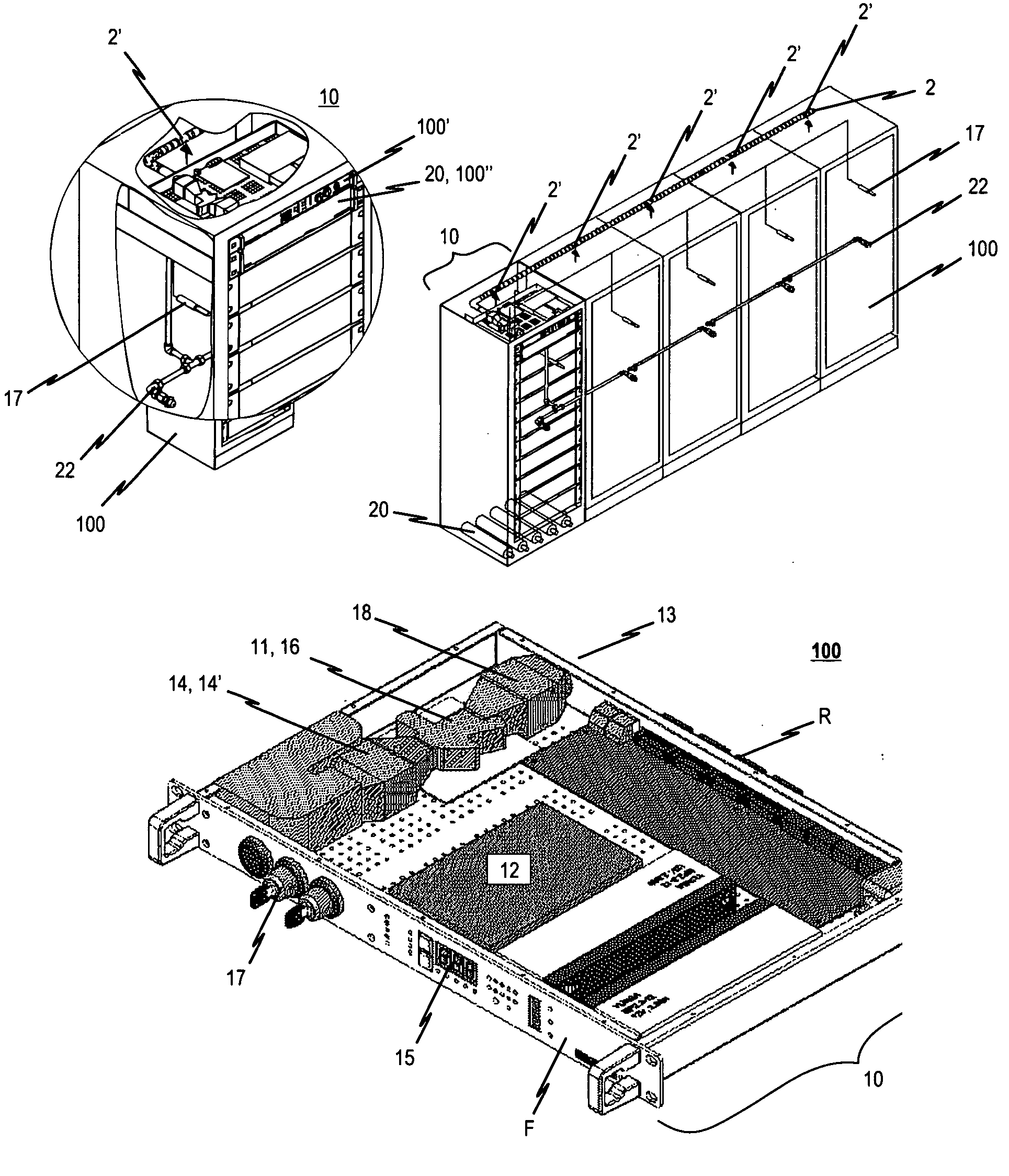
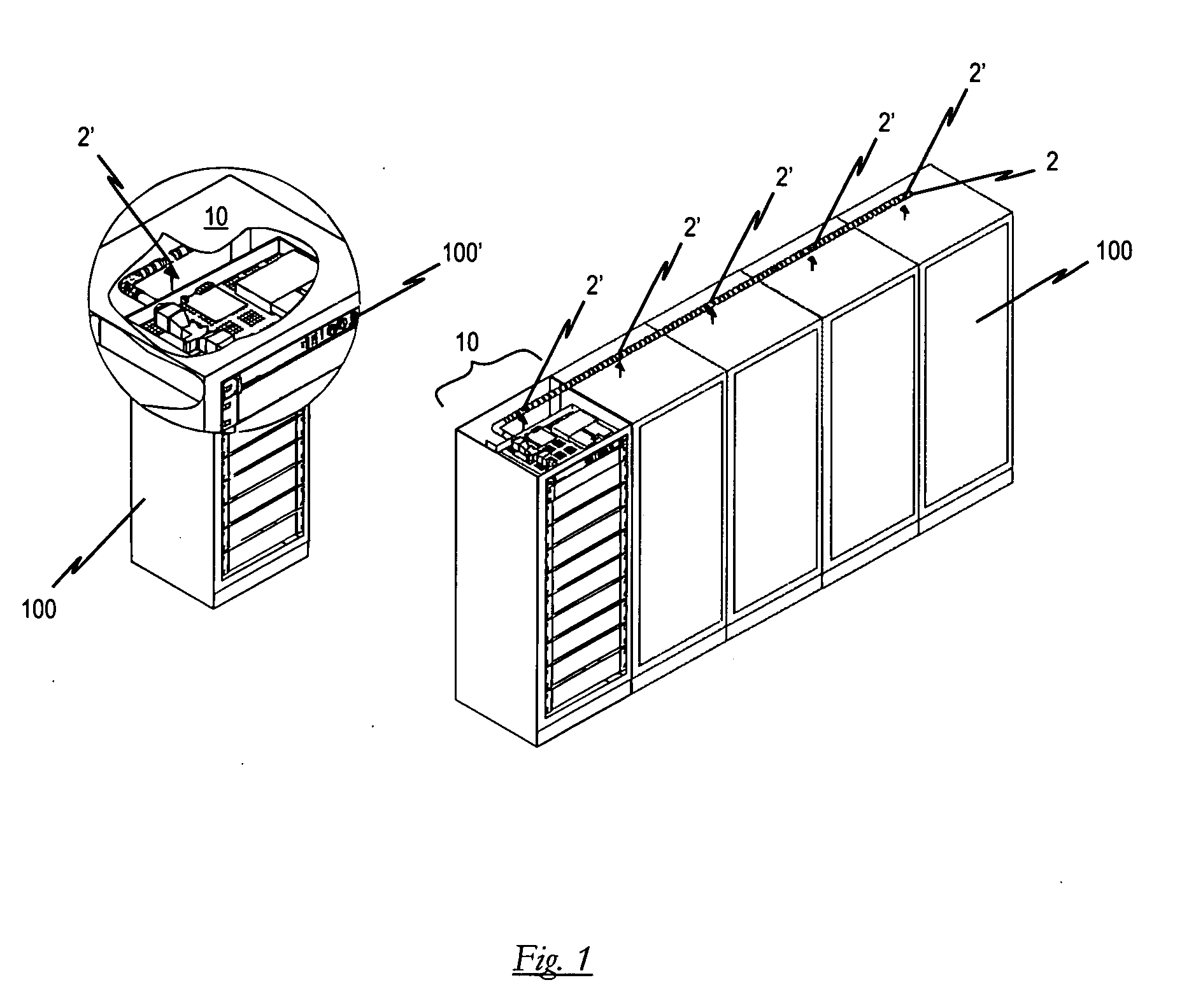
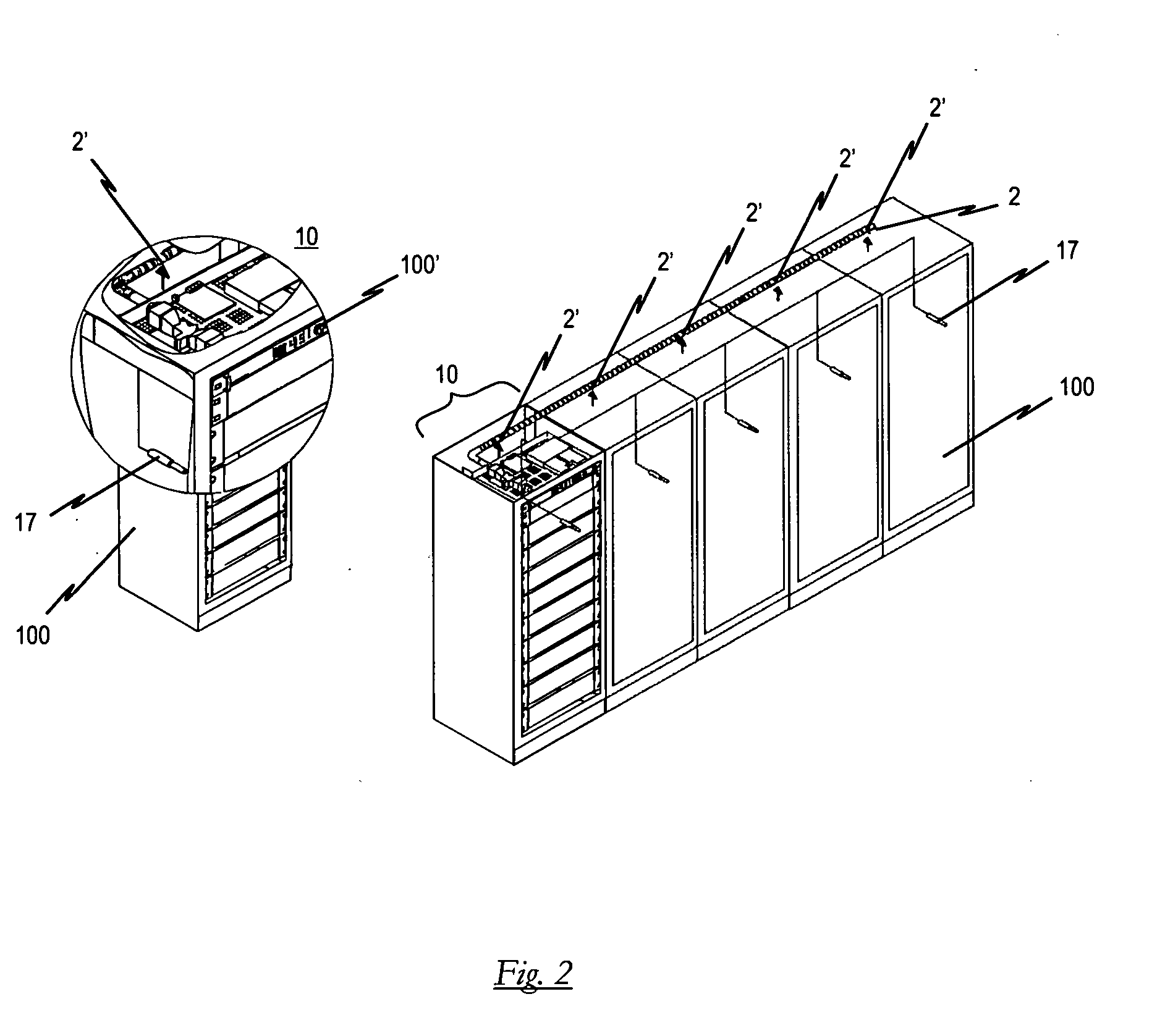
[0055]FIG. 1 shows a schematic view of a first preferred embodiment of the apparatus according to the invention in the installed state, whereby the apparatus is configured as an electrical equipment rack-fire detection apparatus. The electrical equipment rack-fire detection apparatus exhibits a suction pipe system 2 which connects a plurality of adjacently arranged electrical equipment racks 100 (in the embodiment as shown, a total of five electrical equipment racks 100), whereby the suction pipe system 2 communicates with the individual electrical equipment racks 100 to be monitored through respective suction openings 2′. The fire detection apparatus according to this embodiment moreover exhibits an early fire detection module 10 comprising a detector unit 11 (to be described below) for identifying at least one fire parameter in the air sample drawn through the suction pipe system 2 and a controller 12 for emitting an early fire detection signal in response to a detection result re...


PUM


Abstract

An apparatus for fire detection in an electrical equipment rack includes a suction pipe system which communicates with the rack monitored through at least one suction opening and through which a representative air sample is drawn from the rack, an early fire detection module having at least one detector unit for detecting at least one fire parameter in the air sample extracted through the suction pipe system, and a controller for issuing an early fire detection signal in response to the result detected with the at least one detector unit. The early fire detection module is configured as a rackmount to be inserted into the rack.

Description

BACKGROUND OF THE INVENTION [0001] 1. Field of the Invention [0002] The present invention relates to an apparatus for fire detection in an electrical equipment rack comprising a suction pipe system which communicates with the electrical equipment rack to be monitored through at least one suction opening and through which a representative air sample is drawn from the electrical equipment rack to be monitored, an early fire detection module having at least one detector unit for detecting at least one fire parameter in the air sample extracted through the suction pipe system, and a controller for issuing a fire detection signal in response to the result detected with the at least one detector unit. [0003] To be understood by the term “electrical equipment rack” as used here are all cabinets which accommodate electronic components or devices such as e.g. computer system racks, network racks, production control racks, electronic control racks or even telecommunication racks. Furthermore,...

Claims


Application Information

Patent Timeline
Patent Type & Authority Applications(United States)
IPC IPC(8): G08B17/10G08B17/00G08B25/00
CPCA62C3/16G08B17/00G08B17/10H05K7/1495G08B17/113
Inventor WAGNER, ERNST WERNERHELLER, CARSTEN
Owner AMRONA
Why Eureka
Try Eureka