Method and apparatus for rendering semi-transparent surfaces

a technology of semi-transparent surfaces and rendering methods, applied in the field of rendering 3d models, can solve problems such as geometry edges, technique problems, and hidden surfaces, and achieve the effect of avoiding time-consuming processes

Active Publication Date: 2007-05-10
ADOBE INC
View PDF11 Cites 22 Cited by
  • Summary
  • Abstract
  • Description
  • Claims
  • Application Information

AI Technical Summary

Benefits of technology

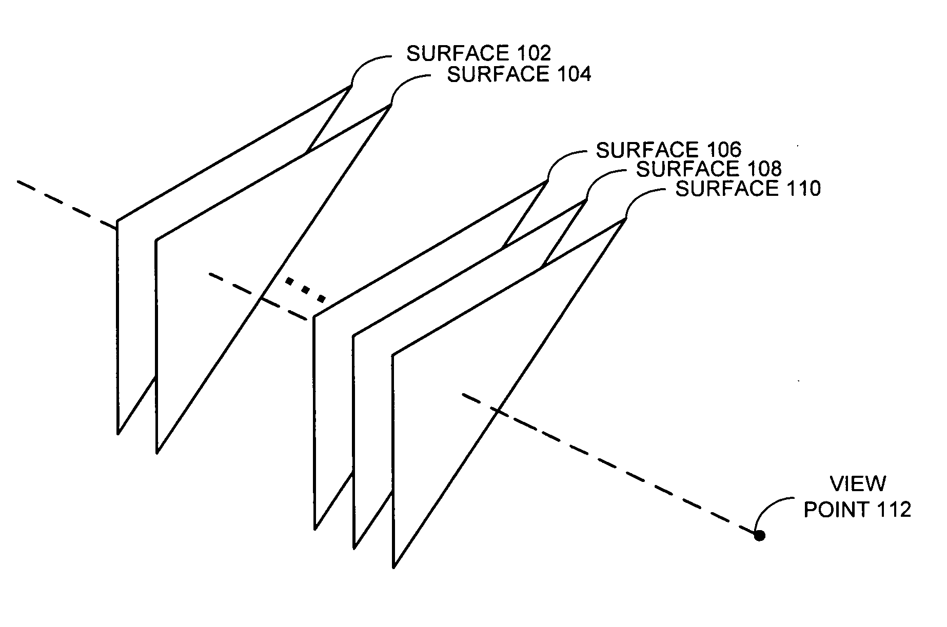
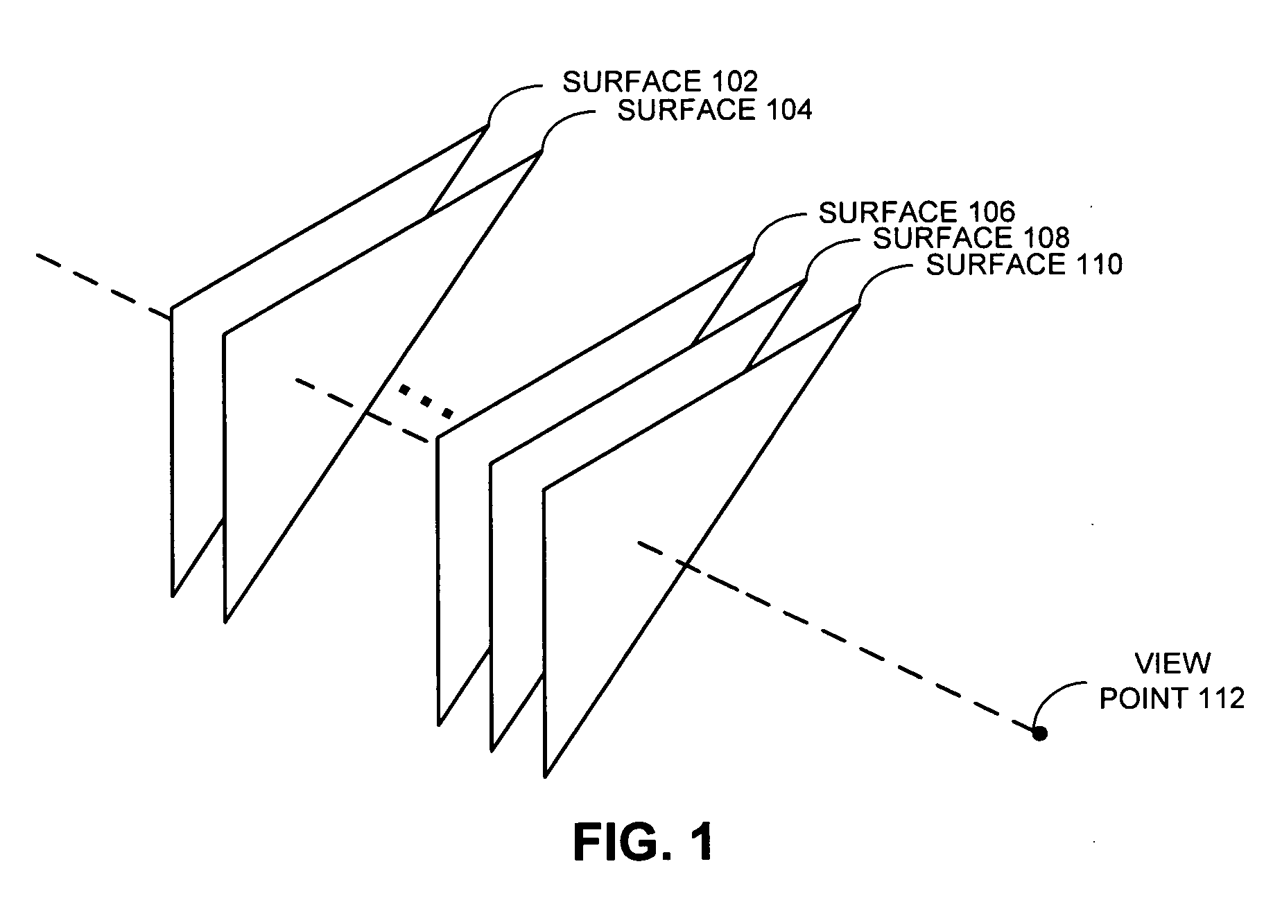
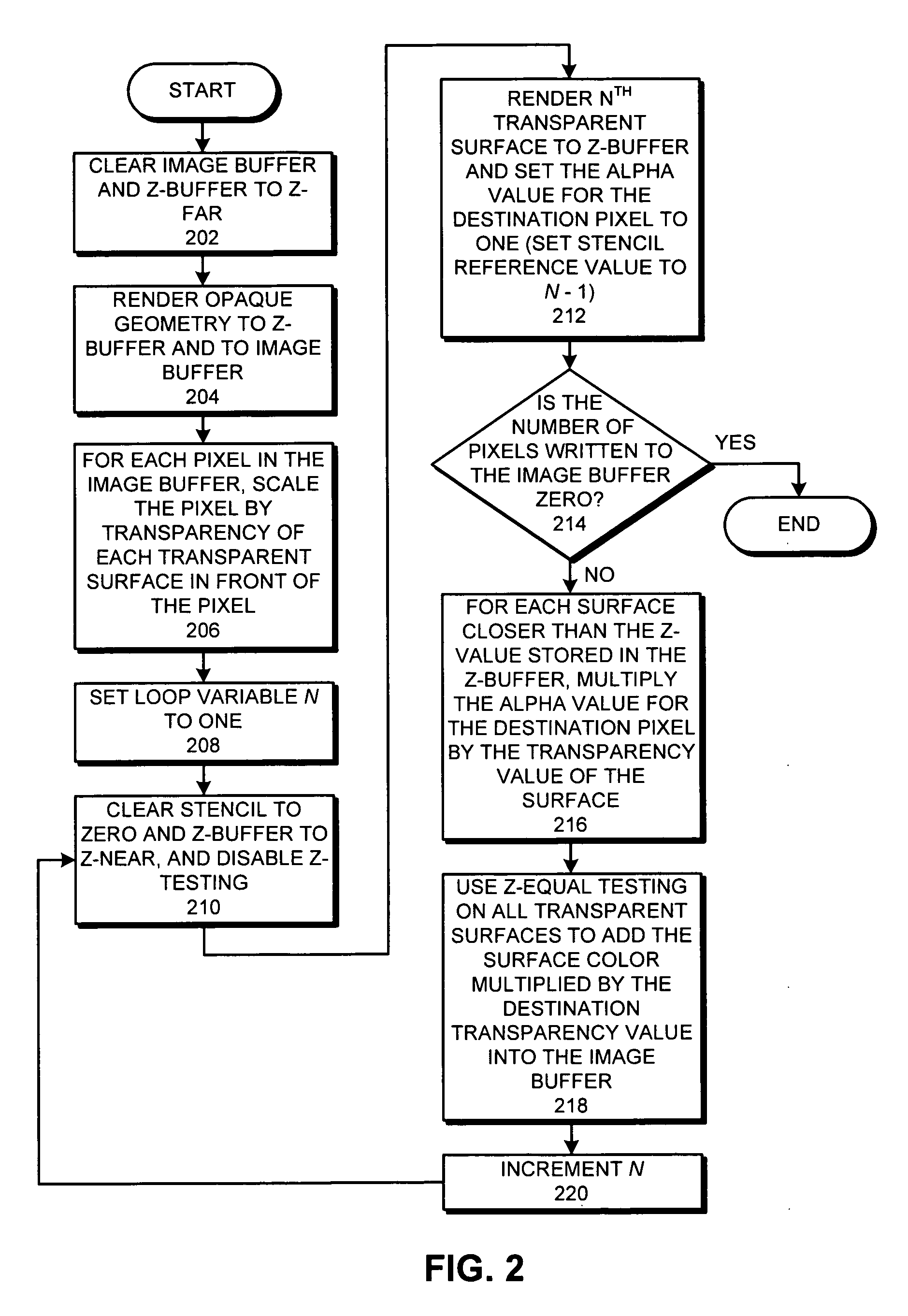
[0010] One embodiment of the present invention provides a system that renders a three-dimensional model which contains semi-transparent surfaces. During operation, the system renders the semi-transparent surfaces in the three-dimensional model by performing the following operations iteratively for each semi-transparent surface in draw-order instead of depth-order: (1) rendering the semi-transparent surface to a Z-buffer, (2) calculating a cumulative transparency value for each pixel of the semi-transparent surface as a function of the transparency value for each opaque and semi-transparent surface that intersects the pixel and is in front of the Z-value for the pixel in the Z-buffer, (3) attenuating a surface color value for each pixel in the semi-transparent surface by the cumulative transparency value for the pixel, and (4) adding the attenuated surface color value to a corresponding pixel value in an image buffer. Note that rendering the semi-transparent surfaces in draw-order instead of depth-order avoids the time-consuming process of sorting the geometries for three-dimensional models to establish a depth-ordering.

Problems solved by technology

A typical problem encountered when rendering 3-D graphics models is “hidden surface” removal, which involves finding the nearest surface at each pixel.
This geometry sort is referred to as an “object space sort.” Unfortunately, this technique can be problematic for complex models containing intersecting surfaces, where the triangles which make up the surface have to be broken up into smaller pieces.
When using the Z-buffer technique to render images, aliasing (i.e. stair-step artifacts) can result on geometry edges.
These pixel shaders are relatively expensive to execute.

Method used


Image

  • Method and apparatus for rendering semi-transparent surfaces
  • Method and apparatus for rendering semi-transparent surfaces
  • Method and apparatus for rendering semi-transparent surfaces

Examples


Embodiment Construction

[0023] The following description is presented to enable any person skilled in the art to make and use the invention, and is provided in the context of a particular application and its requirements. Various modifications to the disclosed embodiments will be readily apparent to those skilled in the art, and the general principles defined herein may be applied to other embodiments and applications without departing from the spirit and scope of the present invention. Thus, the present invention is not limited to the embodiments shown, but is to be accorded the widest scope consistent with the principles and features disclosed herein.

[0024] The data structures and code described in this detailed description are typically stored on a computer-readable storage medium, which may be any device or medium that can store code and / or data for use by a computer system. This includes, but is not limited to, magnetic and optical storage devices such as disk drives, magnetic tape, CDs (compact disc...


PUM


Abstract

A system that renders a three-dimensional model which contains semi-transparent surfaces. During operation, the system renders the semi-transparent surfaces in the three-dimensional model by performing the following operations iteratively for each semi-transparent surface in draw-order instead of depth-order: (1) rendering the semi-transparent surface to a Z buffer, (2) calculating a cumulative transparency value for each pixel of the semi transparent surface as a function of the transparency value for each opaque and semi-transparent surface that intersects the pixel and is in front of the Z-value for the pixel in the Z-buffer, (3) attenuating a surface color value for each pixel in the semi-transparent surface by the cumulative transparency value for the pixel, and (4) adding the attenuated surface color value to a corresponding pixel value in the image buffer.

Description

BACKGROUND [0001] 1. Field of the Invention [0002] The present invention relates to techniques for rendering 3-D models that have semi-transparent surfaces. More specifically, the present invention relates to a method and an apparatus for rendering semi-transparent surfaces in draw-order instead of depth-order. [0003] 2. Related Art [0004] A typical problem encountered when rendering 3-D graphics models is “hidden surface” removal, which involves finding the nearest surface at each pixel. Since the image is created using only the color of the nearest shaded surface at each pixel, hidden surface removal produces a realistic depiction of opaque objects. [0005] One technique for rendering hidden surfaces involves sorting the triangles which make up the surface so that the nearest triangles are rendered last when rasterizing the triangles to the image buffer. Note that an image buffer stores rendered pixels. This geometry sort is referred to as an “object space sort.” Unfortunately, thi...

Claims


Application Information

Patent Timeline
Patent Type & Authority Applications(United States)
IPC IPC(8): G06T15/40
CPCG06T15/405
Inventor MILLER, GAVIN S.
Owner ADOBE INC
Why Eureka
Try Eureka