Pneumatic tire

a technology of pneumatic tires and tyres, which is applied in the field of pneumatic tires, can solve the problems of rust, reducing strength, and eroded cords,

Inactive Publication Date: 2007-05-24
UEYOKO KIYOSHI +2
View PDF1 Cites 19 Cited by
  • Summary
  • Abstract
  • Description
  • Claims
  • Application Information

AI Technical Summary

Problems solved by technology

if small amount of air or moisture penetrates into the bead portion and reaches to the surface of such a cord on which a small separation or adhesion failure occurs, the cord will be eroded.
If the cords are steel cords, the rust may be caused.
If the cord is made of organic fibers, the strength may be decreased as they absorb water, and as the result, there is occasionally seen a cord damage and a separation of the cords from the topping rubber.
However, in the case of heavy-duty tires, as the deformation of the bead portions and the shearing force between cords and rubber are large, sometimes the durability of bead portions is impaired.

Method used


Image

  • Pneumatic tire
  • Pneumatic tire
  • Pneumatic tire

Examples


first embodiment

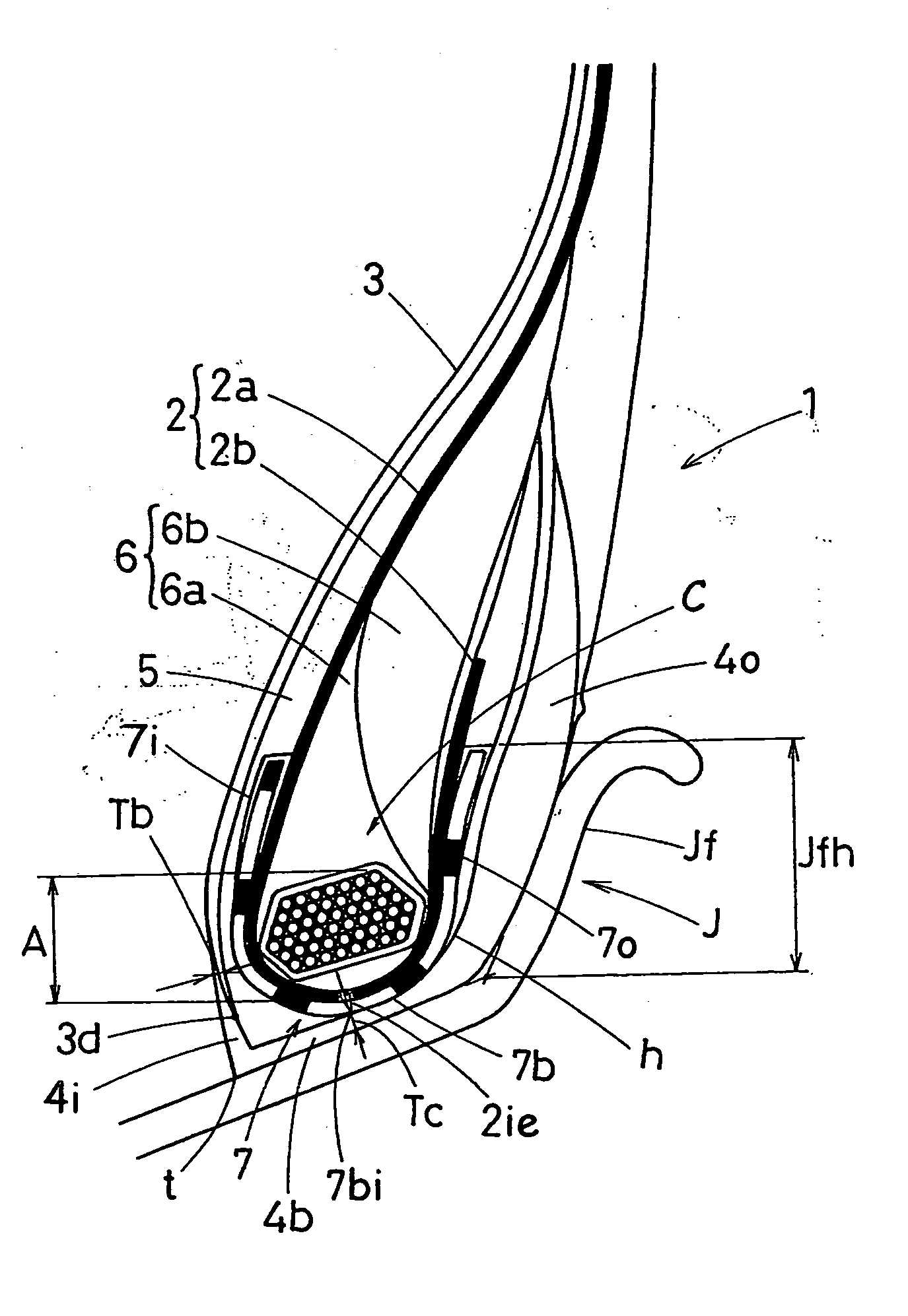
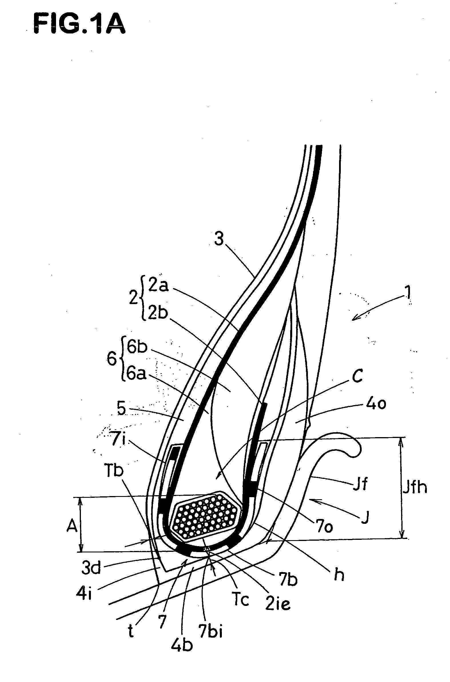
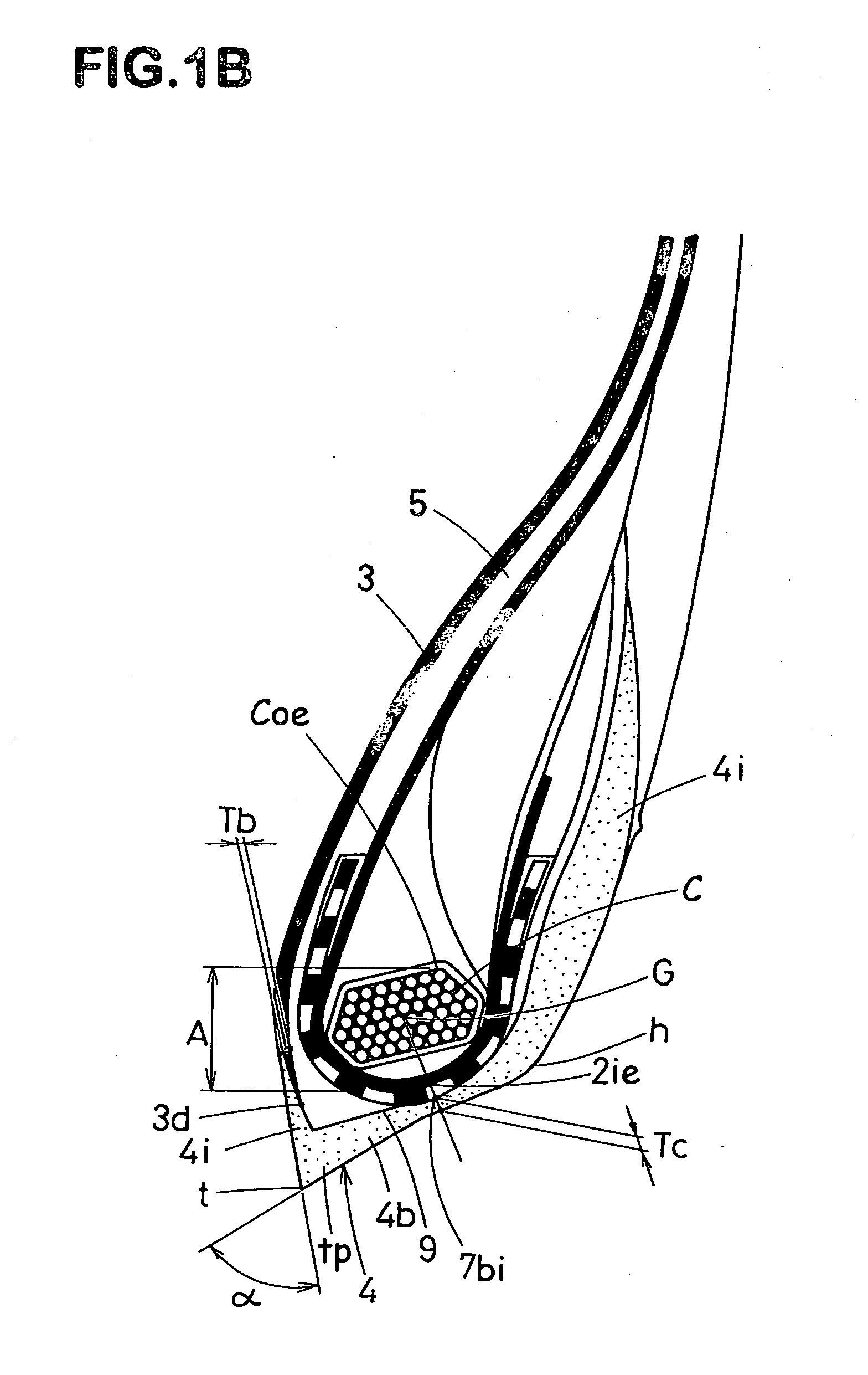
[0029]FIGS. 1A and 1B show a first embodiment of the present invention, wherein FIG. 1A shows a meridian section of the bead portion 1 in a state of the pneumatic tire which is mounted on a standard rim J and inflated to a standard inner pressure but loaded with no tire load (hereinafter the “standard state”), and FIG. 1B shows the meridian section of the bead portion 1 in a free state of the tire which is not mounted on a rim.

[0030] The bead portions 1A are each provided between the ply-main portion 2a and ply-turnup portion 2b of the carcass 2 with the bead apex 6 extending radially outwards from the upper surface of the bead core C.

[0031] The bead apex 6 in this example includes an inner apex 6a disposed adjacent to the bead core and made of a hard rubber, and an outer apex 6b disposed radially outside thereof and being softer than the inner apex.

[0032] The above-mentioned ply-turnup portion 2b is extended radially outwardly along the axially outer surface of the bead apex 6, ...

second embodiment

[0053]FIG. 2 shows a second embodiment of the present invention.

[0054] The bead apex 6 is smaller in volume and size in comparison with the above-mentioned first embodiment, and made up of an equivalent to the above-mentioned inner apex 6a alone.

[0055] The turnup portion 2b of the carcass ply extends along the axial outer surface of the bead apex 6, radially outwardly beyond the upper end 6t of the bead apex 6.

[0056] Between the carcass cords in this portion beyond the upper end 6t and the carcass cords in the carcass-ply main portion 2a, a specific cord distance CS is provided.

[0057] The cord distance Cs in this example increases from the upper end 6t of the bead apex toward the upper end 2t of the turnup-portion 2b. As to the region from the upper end 6t to the upper end 2t, in its ⅓ to ⅔ part from the upper end 6t, the cord distance CS is substantially constant, but in the remainder or radially outer part, the cord distance gradually increases. However, it may be also possibl...

third embodiment

[0062]FIG. 3 shows a third embodiment of the present invention.

[0063] In the bead portion 1, the reinforcing layer 7 having a u-shaped cross-sectional shape same as in the first embodiment is disposed along the carcass 2. The axially inner portion 7i and outer portion 70 of the reinforcing layer 7 are each extended radially outwards of the radially outermost point Coe of the bead core C up to, for example, a height corresponding to the point Coe to which a height of about 0.5 to 2.0 times that of the region (A) is added. Thus, while the carcass 2 is protected, the bending rigidity of the whole bead portion increases, a deformation of the bead portion when loaded is controlled, and strain of each part decreases. As the result, the bead durability of the tire may be improved.

[0064] The reinforcing layer 7 in this embodiment is made up of a single rubberized ply of parallel steel cords. As to the cord angle thereof, when the tire is viewed sideways facing the sidewall portion normall...


PUM


Abstract

A pneumatic tire comprises a tread portion, a pair of sidewall portions, a pair of bead portions, a bead core disposed in each bead portion, a carcass comprising a ply of carcass cords extending between the bead portions through the tread portion and sidewall portions and turned up around the bead core in each bead portion, and an inner liner made of air-impermeable rubber extending on the tire cavity side of the carcass from one of the bead portions to the other. The radially inner end of the inner liner is located radially inside the radially innermost end of the carcass. In a radial region between the radially innermost end of the carcass and the radially outermost end of the bead core, the thickness of the inner liner is not less than 0.15 time but not more than 4.0 times the cross section diameter of the carcass cord.

Description

TECHNICAL FIELD [0001] The present invention relates to a pneumatic tire, more particularly to a structure of the bead portion being capable of improving the durability performance. BACKGROUND ART [0002] In general, an annular bead core, which is disposed in each bead portion of a pneumatic tire to provide a hoop effect, is made of windings of a metal wire wound at a predetermined number of time, and it has a function to secure the carcass ply by turning up the carcass ply around the bead core from the axially inside to the outside of the tire. [0003] On the other hand, the inner surface of a tire is provided with an inner liner of air-impermeable rubber extending over the tread portion, sidewall portions and bead portions in order to maintain an air pressure. [0004] Conventionally, the radially inner end of the inner liner is terminated near the bead cores, and usually, in a region axially inside the bead core the axially inside of the bead portion is not completely covered with th...

Claims


Application Information

Patent Timeline
Patent Type & Authority Applications(United States)
IPC IPC(8): B60C15/06B60C5/14B60C15/00
CPCB60C5/14B60C5/142B60C15/0027Y10T152/10846B60C2200/06B60C2015/0614Y10T152/10828B60C15/06B60C15/0607
Inventor UEYOKO, KIYOSHINISHI, MINORUNUMATA, KAZUKI
Owner UEYOKO KIYOSHI
Why Eureka
Try Eureka