Gas sensors and methods of manufacture

a gas sensor and manufacturing method technology, applied in the field of planar gas sensors, can solve the problems of high raw material costs, high production scrap rate, and manufacturing obstacles of altered designs

Inactive Publication Date: 2007-05-24
DELPHI TECH INC
View PDF3 Cites 19 Cited by
  • Summary
  • Abstract
  • Description
  • Claims
  • Application Information

AI Technical Summary

Problems solved by technology

However, sintered designs are subject to manufacturing obstacles, such as warpage during the sintering process.
Warpage can occur due to several vari...

Method used


Image

  • Gas sensors and methods of manufacture
  • Gas sensors and methods of manufacture
  • Gas sensors and methods of manufacture

Examples


Embodiment Construction

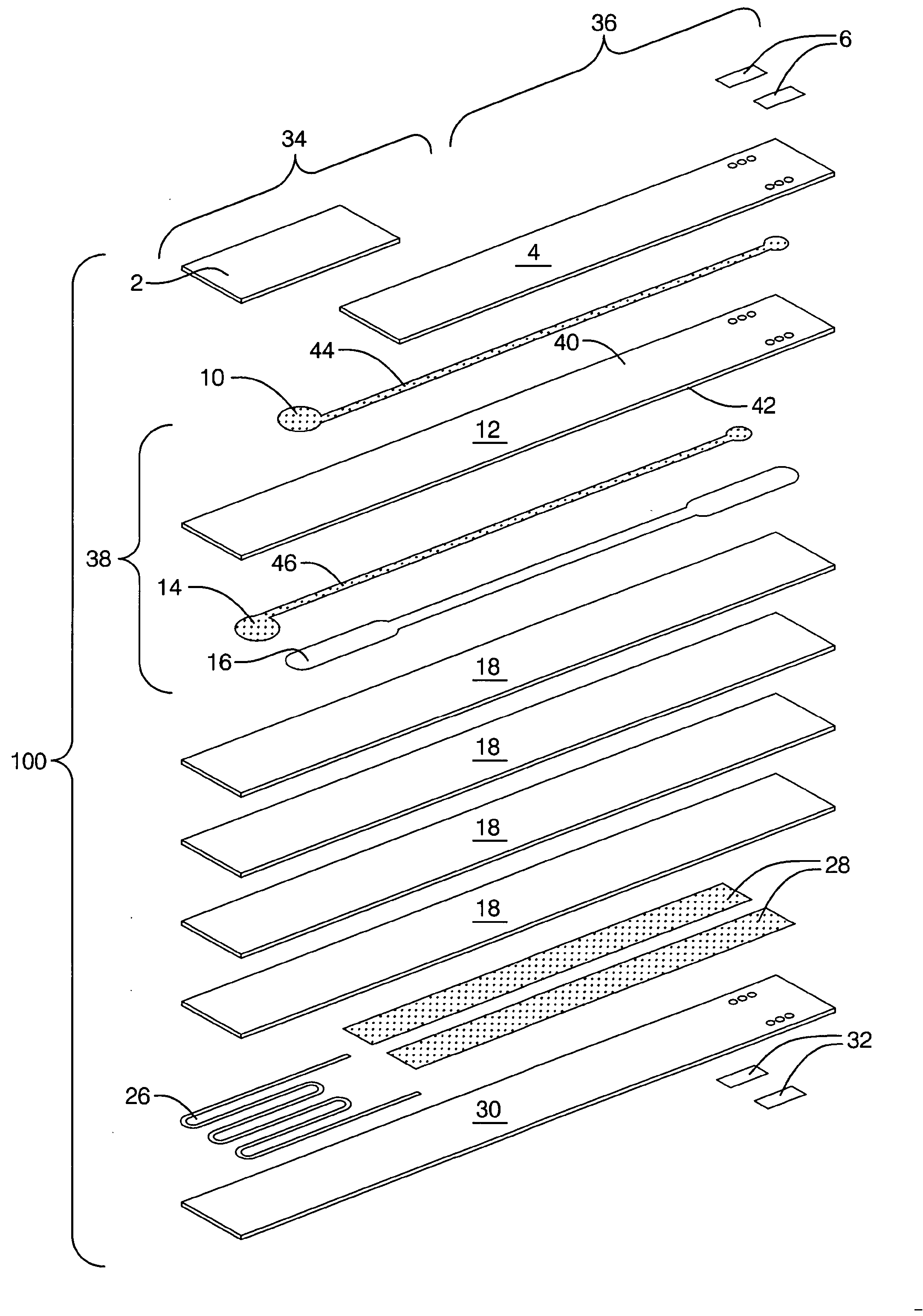
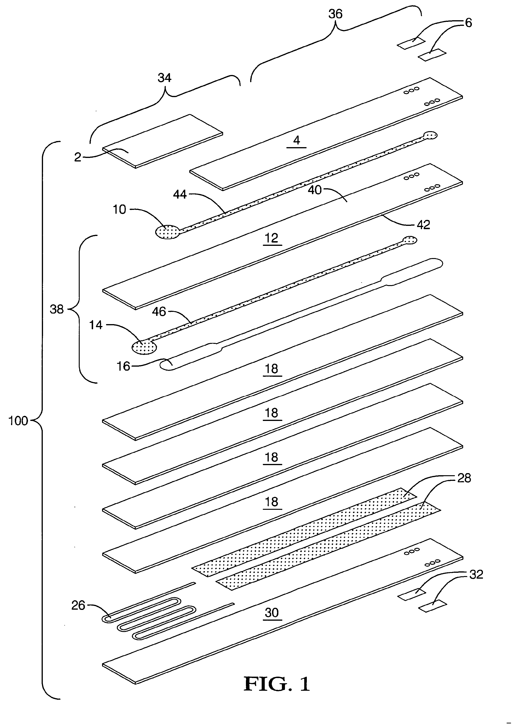
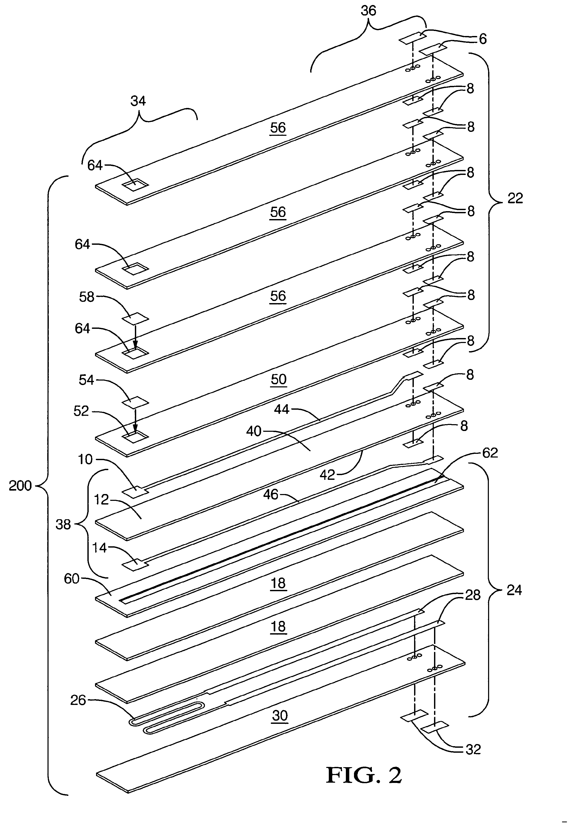
[0011] Disclosed herein are planar gas sensors and methods of manufacture that can reduce or eliminate warpage during sintering. More specifically, designs for planar gas sensors are disclosed which reduce or eliminate warpage by adding and / or removing support layers to attain a more “balanced” design about the electrolyte layer, which can reduce the effects of disproportionate coefficients of shrinkage between layers. In addition, device designs and methods of manufacture are disclosed herein that incorporate a sensor window, which enables an overall reduction in raw material costs of multiple components and also reduces the potential of warpage.

[0012] At the outset, for clarity purposes, it is to be apparent that a plurality of planar gas sensor designs are disclosed herein. It is also to be understood that these devices can also be described as using general terms (e.g. “gas sensors”, “sensors”, “devices”). The modifier “about” used in connection with a quantity is inclusive of ...


PUM


Abstract

Disclosed herein is a gas sensor that comprises a sensor cell, a sensing side support layer, and a reference side support layer. The sensor cell comprises an electrolyte layer, a sensing electrode and a reference electrode, wherein the sensing electrode is disposed on a sensing side of the electrolyte layer, and the reference electrode is disposed on a reference side of the electrolyte layer. The reference side has a reference thickness of about 40% to about 160% of a sensing thickness of the sensing side. Methods for manufacturing gas sensors are also disclosed.

Description

TECHNICAL FIELD [0001] This disclosure generally relates to planar gas sensors and methods of their manufacture. BACKGROUND [0002] Potentiometric gas sensors can be employed in automotive vehicles to monitor the composition of exhaust gases within the exhaust stream. The composition of exhaust gases is of interest as it can provide feedback that allows for the determination of optimum engine operating conditions and exhaust treatment device performance. [0003] Gas sensors can be produced in various configurations, such as, but not limited to, cylindrical and planar designs. In planar designs, the device can be constructed by assembling a plurality of layers into a laminate, which can be co-fired (i.e. sintered) to fuse the layers into a solid sensing element. Although many other processes of assembly can be employed, sintering the laminate can reduce manufacturing and overall part cost. However, sintered designs are subject to manufacturing obstacles, such as warpage during the sint...

Claims


Application Information

Patent Timeline
IPC IPC(8): G01N27/26
CPCG01N27/4071G01N27/4076
Inventor LANKHEET, EARLRUTERBUSCH, PAULQUINN, DAVIDBOLF, FRED
Owner DELPHI TECH INC
Why Eureka
Try Eureka