
Sensor, in particular a magnetic field sensor, with interference compensation and method for interference compensation of a sensor

Active Publication Date: 2007-05-24
AUSTRIAMICROSYSTEMS AG
View PDF8 Cites 25 Cited by
  • Summary
  • Abstract
  • Description
  • Claims
  • Application Information

AI Technical Summary

Benefits of technology

[0023] The method for eliminating the interference signal provides for the interference signal to be filtere

Problems solved by technology

These influence the components of the sensor and corrupt the measurement signal and also the linearity and operating point of the evaluation elements.
Although the detector largely eliminates said offset, the document describes that a considerable inaccuracy

Method used


Image

  • Sensor, in particular a magnetic field sensor, with interference compensation and method for interference compensation of a sensor
  • Sensor, in particular a magnetic field sensor, with interference compensation and method for interference compensation of a sensor
  • Sensor, in particular a magnetic field sensor, with interference compensation and method for interference compensation of a sensor

Examples


Example

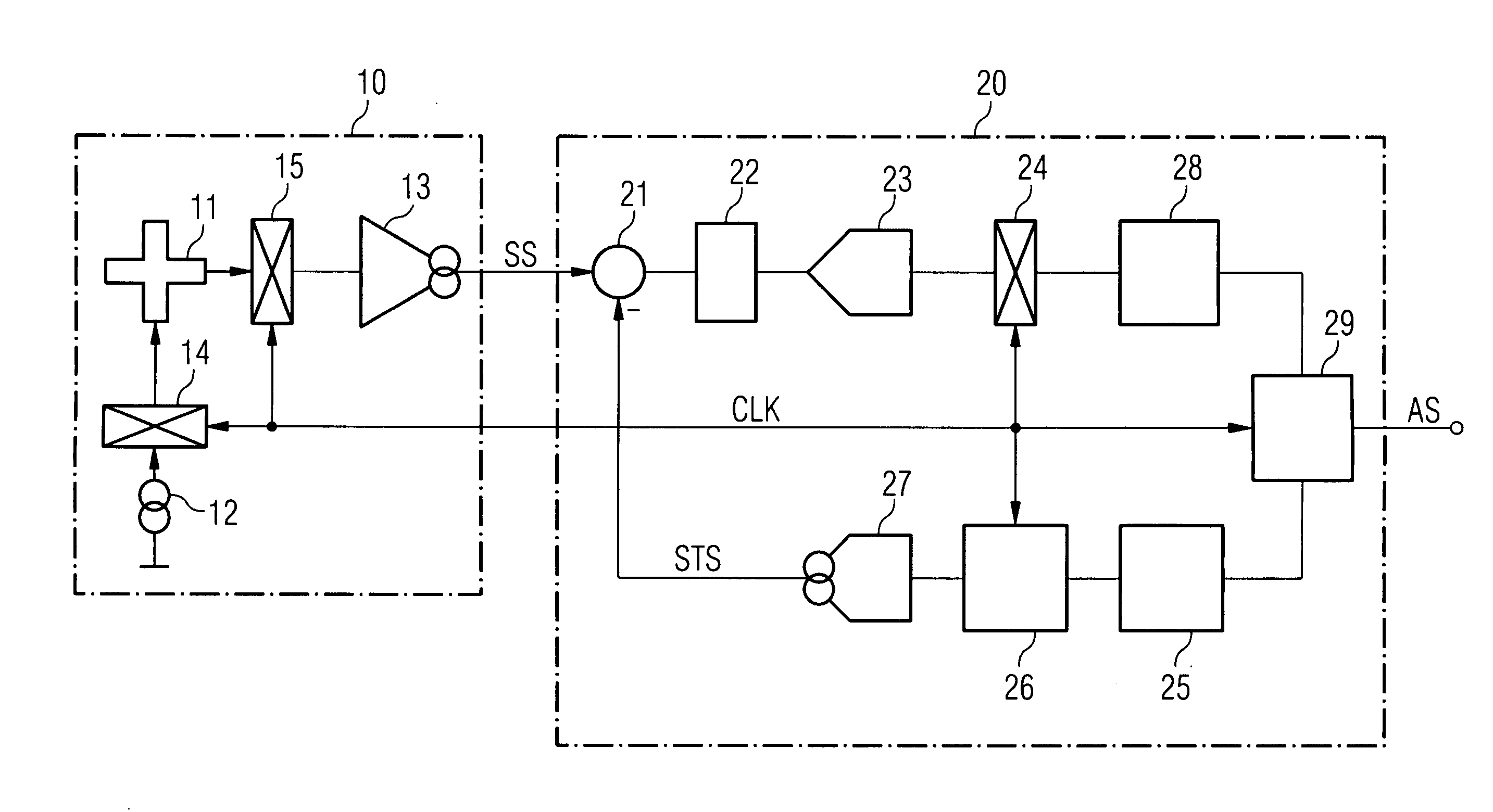
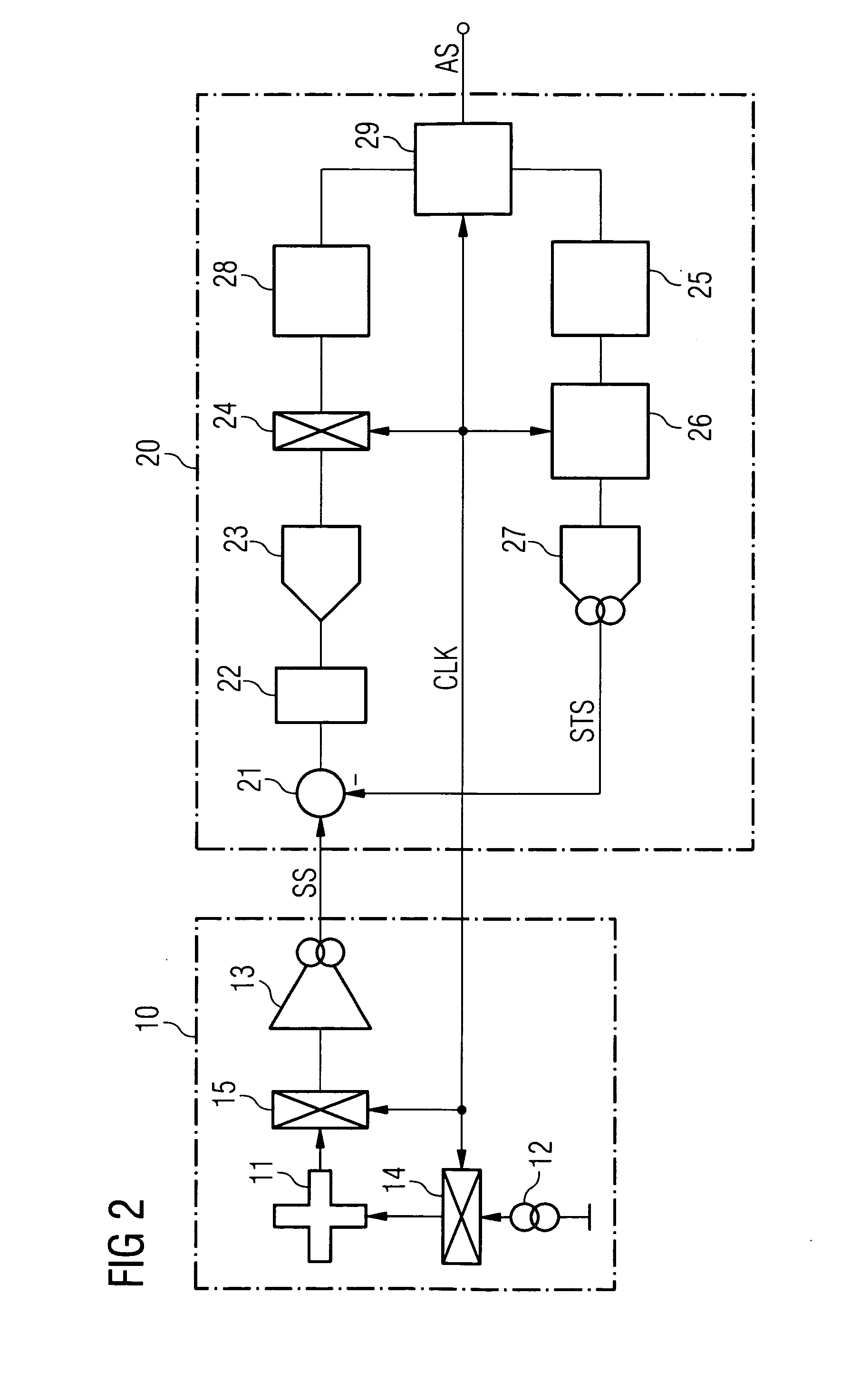
DETAILED DESCRIPTION OF THE DRAWINGS

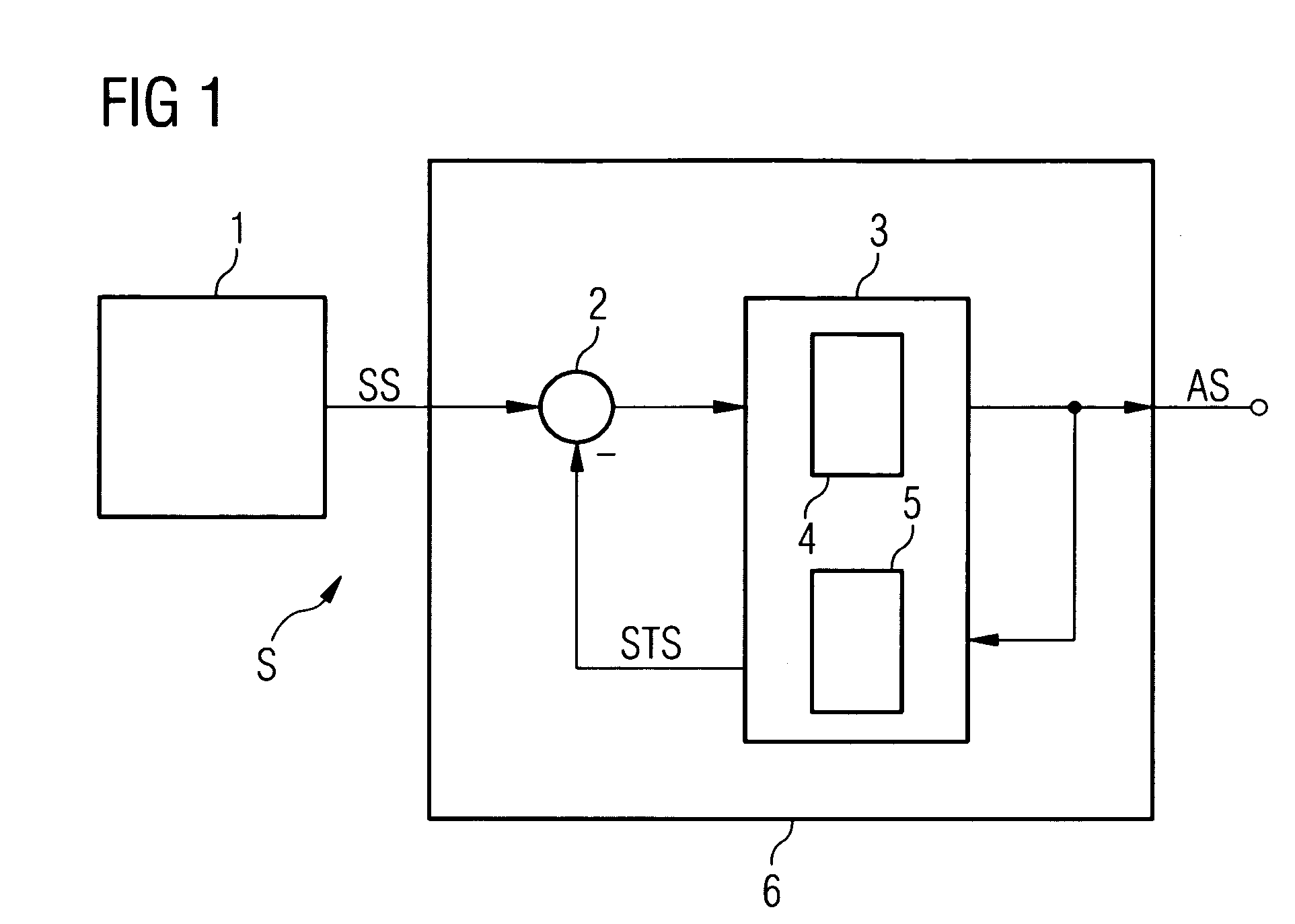
[0027] In accordance with FIG. 1, the sensor S contains a sensor element 1, which detects the measurement quantity to be detected. The sensor signal SS is available at the output of the sensor element and is applied to an input of a subtractor 2 of the evaluation device 6. The output signal of the subtractor passes to a filter device 3 containing a chopper device 4. The chopper alternately generates an inverted partial signal and a noninverted partial signal from the input signal. The chopper frequency is chosen to be correspondingly higher than the highest signal frequency.

[0028] In contrast to what is shown in FIG. 1, the chopper need not be an element of the evaluation device. If the chopper is arranged in the sensor element, e.g. the Hall cell, and upstream of the output amplifier of the sensor element or in the signal path as far as possible directly downstream of the measurement-quantity-sensitive element, interference signal components bo...


PUM


Abstract

A sensor, in particular a Hall sensor, comprising a sensor element (1; 10) which outputs a sensor signal (SS) containing an interference signal (STS). An evaluation device (6; 20) is connected to the sensor element and contains a subtractor (2; 21) which subtracts the interference signal from the sensor signal. The sensor contains a filter device (3), which filters out the interference signal from the sensor signal. The sensor and a related method enable compensation of the interference signal.

Description

RELATED APPLICATIONS [0001] This is a continuation of International Application No. PCT / EP2005 / 000219, filed on Jan. 12, 2005, which claims priority from German Patent Application No. 10 2004 010 362.3, filed on Mar. 3, 2004, the content of which is hereby incorporated by reference.FIELD OF THE INVENTION [0002] The invention relates to a sensor, in particular a magnetic field sensor, comprising a sensor element which outputs a sensor signal containing an interference signal. An evaluation device is connected to the sensor element and contains a subtractor which subtracts a compensation signal from the sensor signal. The invention furthermore relates to a method for interference signal compensation of a sensor. BACKGROUND OF THE INVENTION [0003] A sensor and its evaluation circuit used to evaluate the sensor signal quite generally have interference signals that are superposed on the useful signal that is actually to be generated, i.e. the measurement signal. These include, in particu...

Claims


Application Information

Patent Timeline
IPC IPC(8): G01B7/30G08B13/24G01D3/036G01D5/14
CPCG01D3/036G01D5/142
Inventor ROSSMANN, SIEGFRIEDSTEELE, COLINURBAN, MARCEL
Owner AUSTRIAMICROSYSTEMS AG
Learn More