Default route coding

a technology of default route and coding, applied in the field of default route, can solve the problem of reducing the number of available ip addresses, and achieve the effect of reducing the time available for searching the route tabl

Active Publication Date: 2007-05-24
CHARTOLEAUX
View PDF13 Cites 24 Cited by
  • Summary
  • Abstract
  • Description
  • Claims
  • Application Information

AI Technical Summary

Benefits of technology

[0019]FIG. 2B is the binary tree representation shown in FIG. 2A with an additional route. As shown, route r3 has been added to subtree A in level_2200. Thus, route r0 changes to route r3 for nodes in subtrees A, B and C. The default route for nodes in subtree B in level_3202 and subtree C in level_4204 must be modified to store route r3 instead of route r0. Thus, nodes 2061-2064 and 2069-20616 in subtree B in level_3202 and nodes 2101-2106 and 2109-21016 in subtree C in level_4204 must be modified to store route r3 instead of route r0. The number of updates required when a route is added to the multi-level lookup table decreases the time available for searching the route table.

Problems solved by technology

However, dividing the IP address space into different classes reduced the number of available IP addresses.

Method used


Image

  • Default route coding
  • Default route coding
  • Default route coding

Examples


Embodiment Construction

[0038] A description of preferred embodiments of the invention follows.

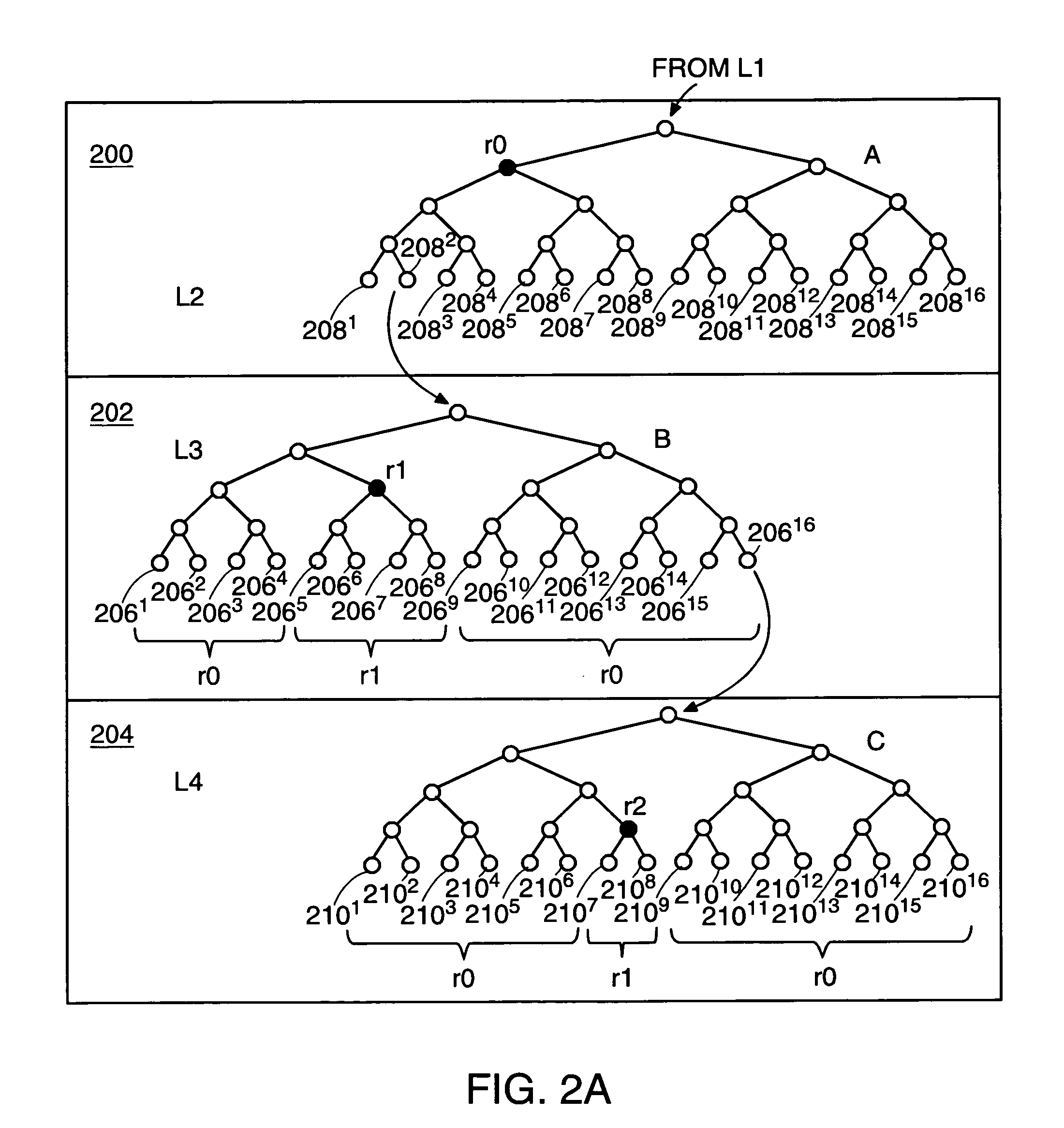
[0039]FIG. 3A is a binary tree representation of routes stored in a multi-level lookup table, with each subtree including a default route memory 306, 308 according to the principles of the present invention. Three levels 300, 302, 304 of the binary tree representation of the multi-level lookup table are shown. Level_2300 includes subtree D. Level_3302 includes subtree E and level_4304 includes subtree F. Node 3142 in subtree D and node 31216 in subtree E store subtree indexes to a subtree in a lower level. Node 3142 stores a subtree index to subtree E and node 31216 stores a subtree index to subtree F.

[0040] The multi-level lookup table stores a subtree descriptor for each subtree. Subtree descriptors are described in co-pending U.S. patent application Ser. No. 09 / 886,649 entitled “Method And Apparatus For Logically Expanding The Width Of Memory”, filed on Jun. 21, 2001, the contents of which are included herei...


PUM


Abstract

A multi-level lookup table includes a plurality of search levels with each search level including a plurality of subtrees, each subtree representing a plurality of nodes. A search of the multi-level lookup table for an entry corresponding to a search key results in a value stored in an entry associated with the node in a subtree. A default value is associated with the root of the subtree. Multiple entries for the subtree can store the default value. To minimize route update time, the default value associated with the subtree is stored in a single location. Instead of storing the default value in multiple entries, each entry stores a use default indicator to indicate that the default value stored in the single location is to be used. To further reduce the number of locations to modify to update the default route, the single location can store an inherit indicator to indicate that the default value for the subtree is inherited from another subtree.

Description

RELATED APPLICATIONS [0001] This application is a continuation of U.S. application Ser. No. 10 / 004,280 filed on Oct. 31, 2001, which claims the benefit of U.S. Provisional Application No. 60 / 258,436, entitled “Algorithm IPv4 Longest Prefix Match (LPM)” filed on Dec. 27, 2000 and U.S. Provisional Application No. 60 / 294,387 entitled “Load Balancing in IP Address Lookup” filed May 30, 2001. The entire teachings of the above applications are incorporated herein by reference.BACKGROUND OF THE INVENTION [0002] The Internet is a set of networks connected by routers. A router maintains a routing table that indicates for each possible destination network, the next hop to which a received data packet should be forwarded. The next hop may be another router or the final destination. [0003] An Internet Protocol (“IP”) data packet received at a port in a router includes an IP destination address. The IP destination address is the final destination of the IP data packet. Currently there are two ve...

Claims


Application Information

Patent Timeline
Patent Type & Authority Applications(United States)
IPC IPC(8): H04L12/56G06F15/173H04L12/24H04L29/02
CPCH04L45/745
Inventor BROWN, DAVID A.
Owner CHARTOLEAUX
Why Eureka
Try Eureka