
Flexible circuit shields

Inactive Publication Date: 2007-05-31
MOTOROLA INC
View PDF11 Cites 11 Cited by
  • Summary
  • Abstract
  • Description
  • Claims
  • Application Information

AI Technical Summary

Benefits of technology

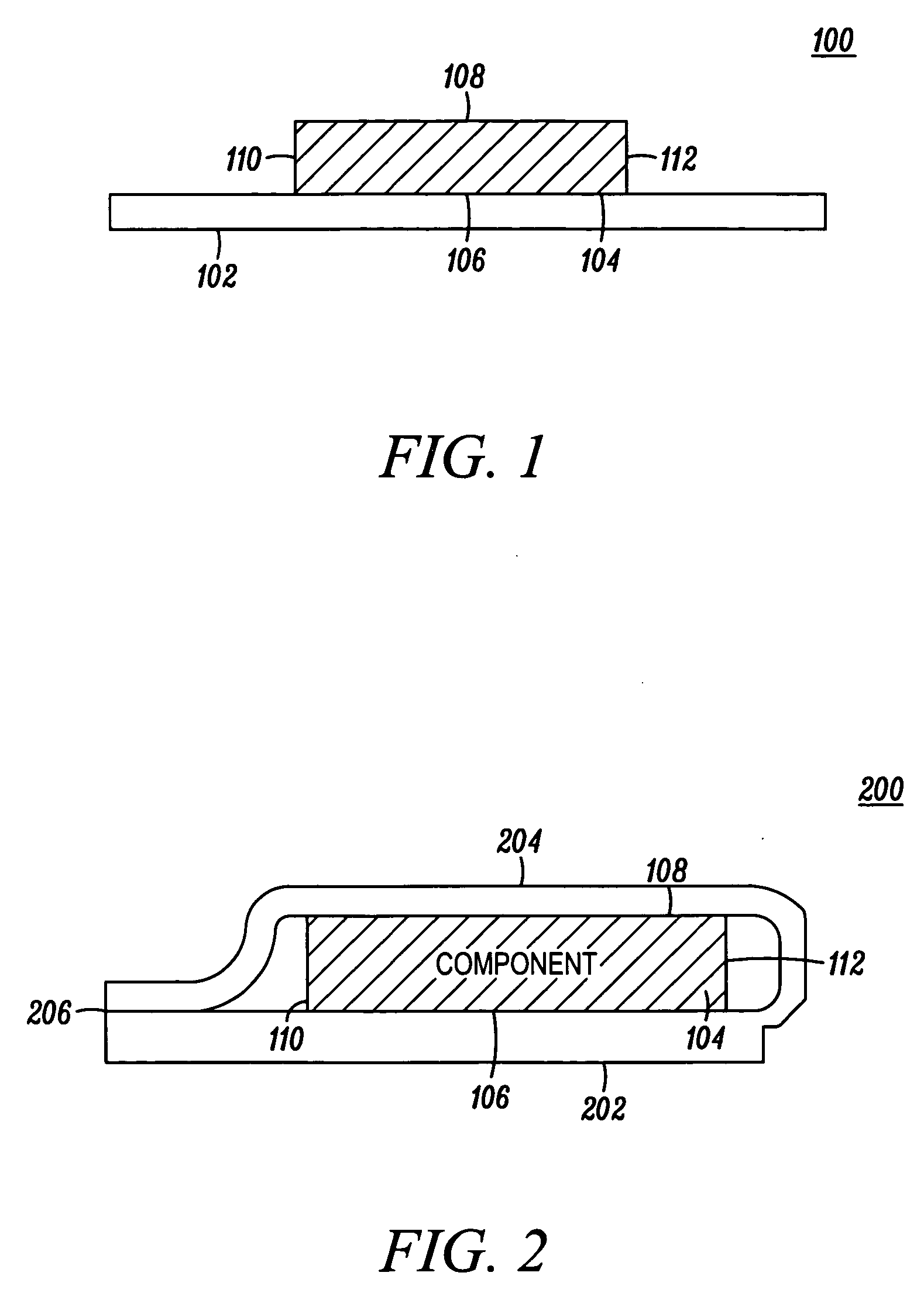
[0009] In another arrangement, covering the exposed surface of the electrical component can include covering the exposed surface in a manner such that a gap can be formed between the exposed surface of the electrical component and the second portion covering the exposed surface. Also, covering the exposed surface can include securing the second portion covering the exposed surface to the exposed surface with an adhesive. Additionally, the method can also include the steps of mounting another electrical component on top of the second portion shielding the electrical component and routing signals from one part of the electrical component to another part of the electrical component, or another electrical component, through signal layers, wi

Problems solved by technology

The electrical components used in the flexible circuits may produce electromagnetic interference (EMI) and radio frequency interference (RFI).
Electromagnetic interference refers to interference caused by th

Method used


Image

  • Flexible circuit shields
  • Flexible circuit shields
  • Flexible circuit shields

Examples


Embodiment Construction

[0020] While the specification concludes with claims defining the features of the invention that are regarded as novel, it is believed that the invention will be better understood from a consideration of the following description in conjunction with the drawing figures, in which like reference numerals are carried forward.

[0021] As required, detailed embodiments of the present invention are disclosed herein. However, it is to be understood that the disclosed embodiments are merely exemplary of the invention, which can be embodied in various forms. Therefore, specific structural and functional details disclosed herein are not to be interpreted as limiting, but merely as a basis for the claims and as a representative basis for teaching one skilled in the art to variously employ the present invention in virtually any appropriately detailed structure. Further, the terms and phrases used herein are not intended to be limiting, but rather to provide an understandable description of the i...


PUM


Abstract

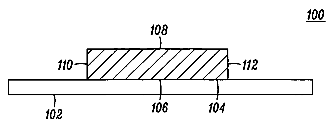
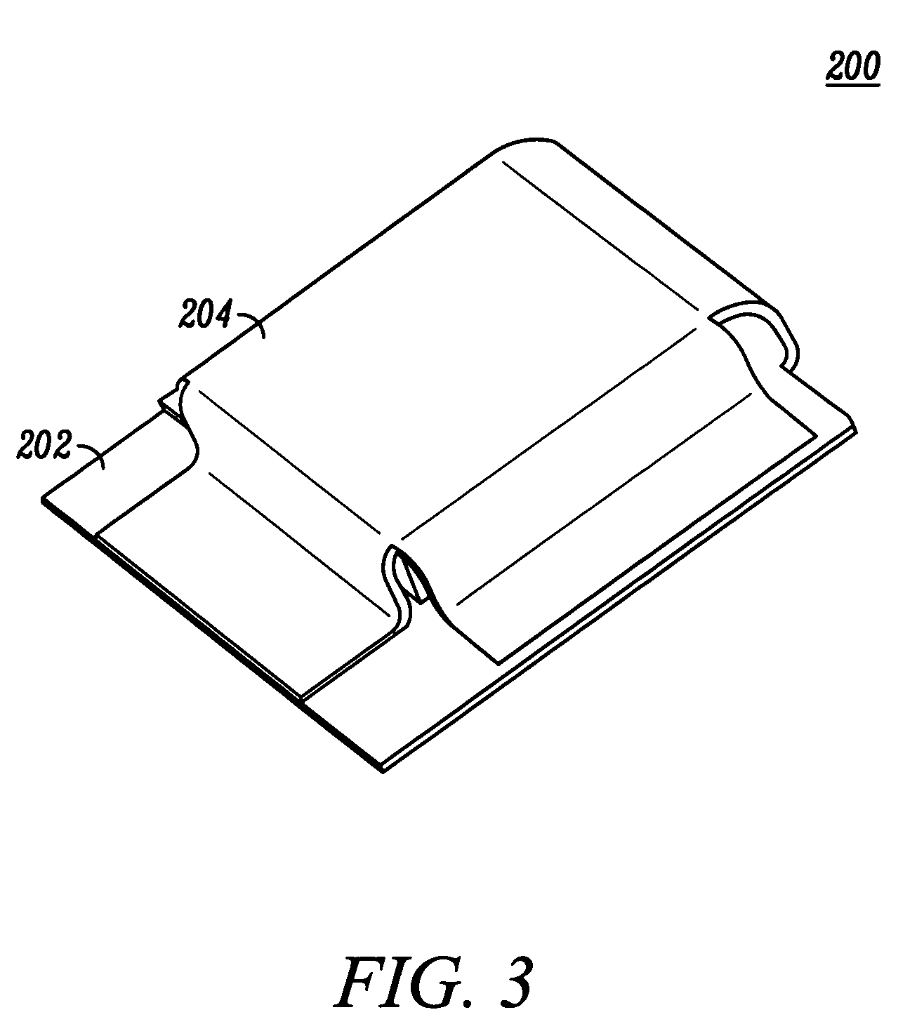
The invention concerns a method (600) and systems (200, 400, 500) for shielding at least one electrical component (104) by using a flexible shielding circuit (102). In one arrangement, the method can include the steps of mounting (604) the electrical component on a first portion (202) of the flexible shielding circuit and covering (606) at least one exposed surface of the electrical component with a second portion (204) of the flexible shielding circuit. Additionally, the method can also include the step of selectively securing (608) the second portion to the first portion with a conductive adhesive (206).

Description

BACKGROUND OF THE INVENTION [0001] 1. Field of the Invention [0002] The present invention relates in general to the field of flexible circuits, and more particularly to the field of shielding electrical components in flexible circuits. [0003] 2. Description of the Related Art [0004] A flexible circuit includes a flexible material that has one or more metal circuit patterns. The flexible material may be single-layered or multi-layered, depending on the number of metal circuit patterns that are insulated from one another by flexible polymer films. The metal circuit patterns include electrical signal paths and ground planes that are embedded in the flexible material. The metal circuit patterns can be interconnected through vias. As is known in the art, a via refers to a metal-plated through hole that connects two or more metal circuit patterns, allowing signals to pass through the flexible material to the signal layers or the ground planes. Several electrical components that can be pas...

Claims


Application Information

Patent Timeline
IPC IPC(8): H05K9/00
CPCH05K1/0218H05K1/189H05K9/0024H05K2201/056H05K9/0043
Inventor RODRIGUEZ, JOSECASTANEDA, JULIONGUYEN, BACH
Owner MOTOROLA INC
Learn More