Method and system for optimizing radio frequency identification (RFID) reader operation

a radio frequency identification and reader technology, applied in the field of radio frequency identification (rfid), can solve the problems of inefficiency in detection and/or monitoring of tags

Inactive Publication Date: 2007-06-07
SYMBOL TECH INC
View PDF12 Cites 82 Cited by
  • Summary
  • Abstract
  • Description
  • Claims
  • Application Information

AI Technical Summary

Problems solved by technology

If there is a large disparity between the number of tags in a population and the number of available time slots, the detection and/or monitoring of the tags can be inefficient by spending unpro

Method used


Image

  • Method and system for optimizing radio frequency identification (RFID) reader operation
  • Method and system for optimizing radio frequency identification (RFID) reader operation
  • Method and system for optimizing radio frequency identification (RFID) reader operation

Examples


example rfid reader

[0063]FIG. 7 illustrates an example RFID reader 700 that may be used according to an embodiment of the invention. In this example, RFID reader 700 includes RFID controller 702, processor 704, memory 706, encoder 708, modulator 710, decoder 712, demodulator 714, transmission antenna(e) 716 and receive antenna(e) 718. Although not shown in FIG. 7, an RF front-end may also be included in reader 700.

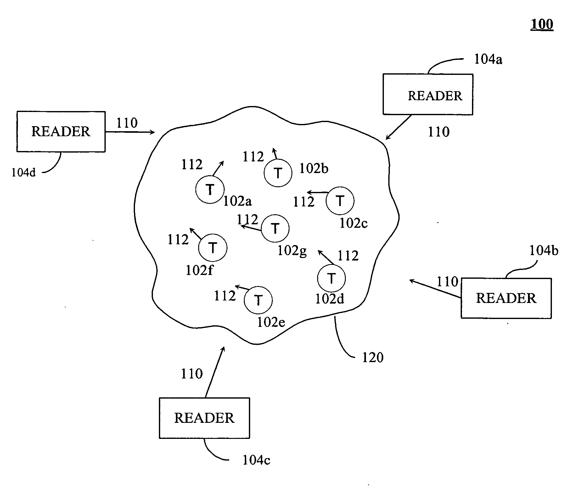
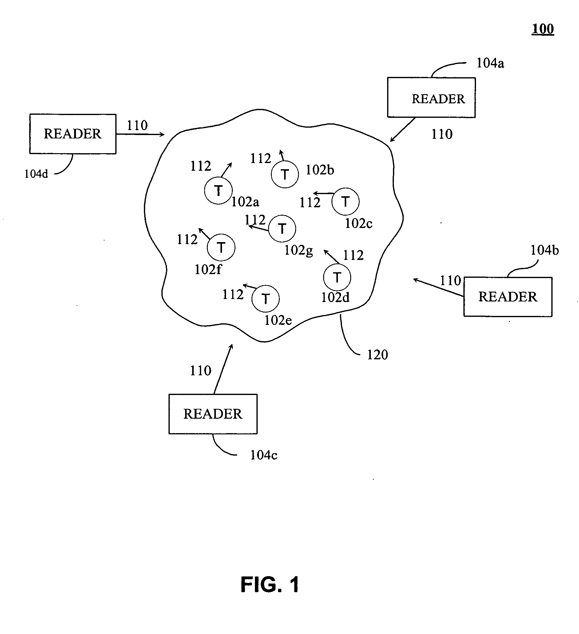
[0064] RFID controller 702 provides information, such as interrogations and commands, to tags. The reader information is encoded by encoder 708, modulated by modulator 710 and transmitted by antenna 716. Radio frequency responses are received from a tag population by antenna 718. The tag responses are demodulated by demodulator 714 and decoded by decoder 712. RFID controller 702 processes the decoded responses. In the current embodiment, RFID controller 702 includes a processor 704 and associated memory 706 in addition to any other circuitry required for an RFID reader (not shown). Processo...


PUM


Abstract

Methods and apparatuses are described for optimizing an interrogation of a radio frequency identification (RFID) tag population. An RFID reader sets an initial number of time slots used to interrogate a population of tags. The reader does not previously know the size of the tag population. The reader monitors responses of tags for one or more time slots of an interrogation round to collect statistical data, estimates a number of tags in the population based on the statistical data, and determines a new number of time slots based on the estimated number of tags. The reader adjusts the number of time slots accordingly for a subsequent interrogation round. The reader may repeat this process as needed to converge closer to the actual number of tags in the population, and an acceptable number of time slots, to enhance an efficiency of the process of interrogating the tag population.

Description

BACKGROUND OF THE INVENTION [0001] 1. Field of the Invention [0002] The present invention generally relates to radio frequency identification (RFID) and more specifically relates to an RFID reader. [0003] 2. Background Art [0004] Radio frequency identification (RFID) tags are electronic devices that may be affixed to items whose presence is to be detected and / or monitored. The presence of an RFID tag, and therefore the presence of the item to which the tag is affixed, may be checked and monitored by devices known as “readers.” Readers typically transmit radio frequency signals to which the tags respond. Each tag can store a unique identification number. The tags respond to the reader transmitted read signals by providing their identification number, so that they can be identified. [0005] According to one example communications protocol, tags in a population respond to the reader during one of a multitude of time slots in a read cycle. Each tag is designated to respond to the reader ...

Claims


Application Information

Patent Timeline
IPC IPC(8): H04Q5/22
CPCG06K7/0008G06K7/10039
Inventor BANDY, WILLIAM R.
Owner SYMBOL TECH INC
Why Eureka
Try Eureka