This helps you quickly interpret patents by identifying the three key elements:
Problems solved by technology
Method used
Benefits of technology
Benefits of technology
[0011] It is a main object of the present invention to provide an assembly of a tire and a rim
Problems solved by technology
Therefore, there is a tendency that a crack and damage are prone to be generated in the sponge material in the vicinity of the outer end of the fixing surface.
As an output of a vehicle is improved and the length of the expressway is increased, there is a tendency that the average running speed of vehicles is also increased, and a large force is prone to be applied to a noise damper fixed to a cavity surface of a tire.
However, when the noise damper a to which the double-faced tape is pasted is packed in a box and transported from a producing factory to a tire producing factory , the noise damper a is deviated in position in the box by vibration and acceleration at the time of transportat
Method used
Image
Click on the blue label to locate the original text in one second.
Reading with bidirectional positioning of images and text.
Examples
Example
EXAMPLE 1
(1) Noise Damper Test:
[0083] Noise dampers 4 having double-faced tapes 11 which have cross section size shown in FIG. 9 and in which both outer ends 4E in the circumferential direction are formed with inclined surface portions 30 having specification shown in Table 1 were prototyped.
[0084] A hundred noise dampers 4 were prototyped, and five of them were arranged in two stages as one unit. Ten units were packed in boxes of inner size (width of 540 mm×height of 335 mm×length of 1990 mm), and they were transported from Aichi prefecture to Fukushima prefecture. The noise dampers 4 are carried such that their longitudinal direction intersects with a moving direction of the truck.
[0085] The noise dampers 4 after transportation were checked, the noise damper from which the peeling off paper is peeled off in the tip end P of the inclined surface portion 30 was evaluated as a damaged product, and the generating ratio of the damaged product was compared.
[0086] Each of the noise...
Example
EXAMPLE 2
[0094] Pneumatic tires having the noise dampers were prototyped based on the specification shown in Table 2.
[0095] Pneumatic tires having the noise dampers having substantially the same specification as that of the first embodiment were used.
[0096] Tire size: 215 / 45ZR17
[0097] width BW of belt layer: 166 mm
[0098] Air pressure: 230 kPa
[0099] Rim size: 17×7JJ [0100] Noise damper
[0101] specification of corner of free surface is as shown in Table 2.
[0102] Length L in the circumferential direction of tire: 1840 mm
[0103] Both ends were cut at taper angle θ of 45 degrees and an end was cut with S=5 mm (FIG. 7(B)).
[0104] Fixing method: a long noise damper was curved along a tread region of a cavity surface of the tire and was pasted using a double-faced tape (“E700” produced by Ebisu-chemical. co)
[0105] The double-faced tape has the same size as that of the fixing surface of the noise damper.
[0106] The test method is as follows:
[0107] The pneumatic tires having the nois...
PUM
Abstract
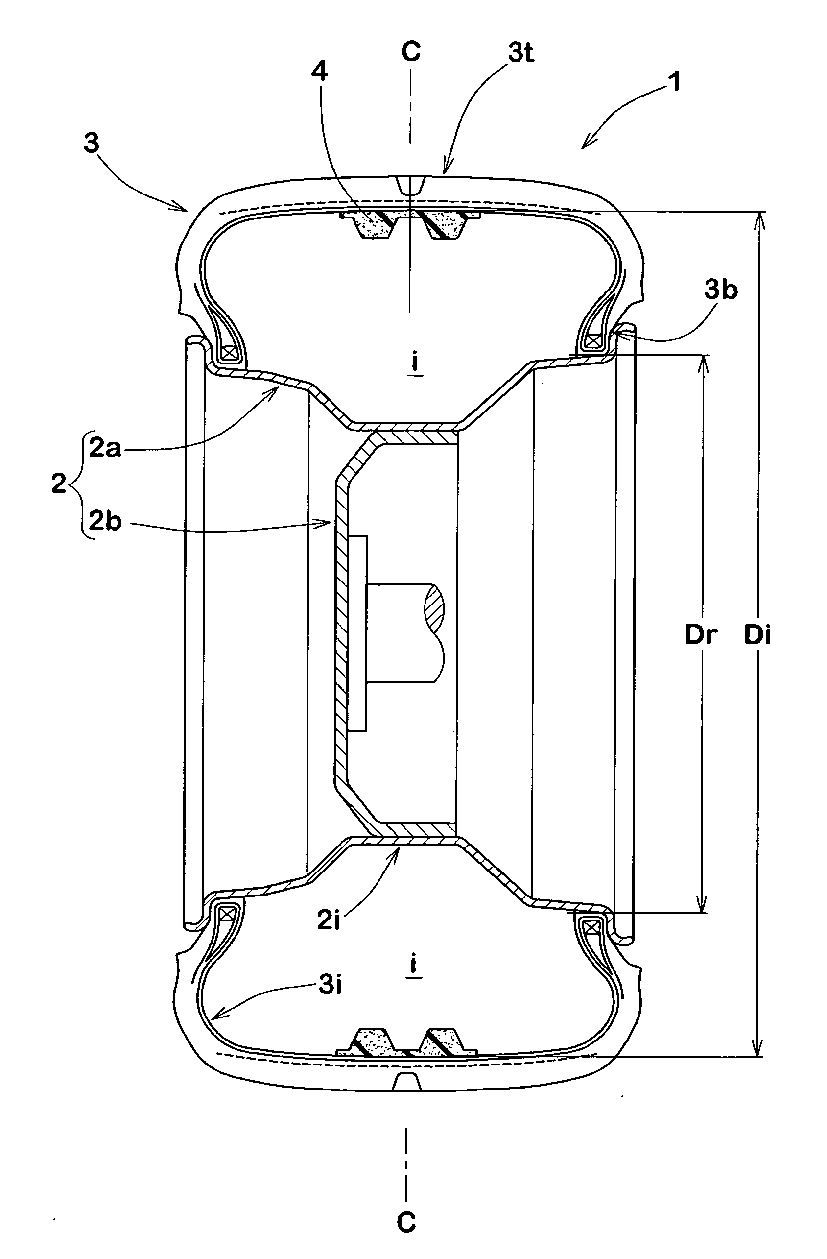
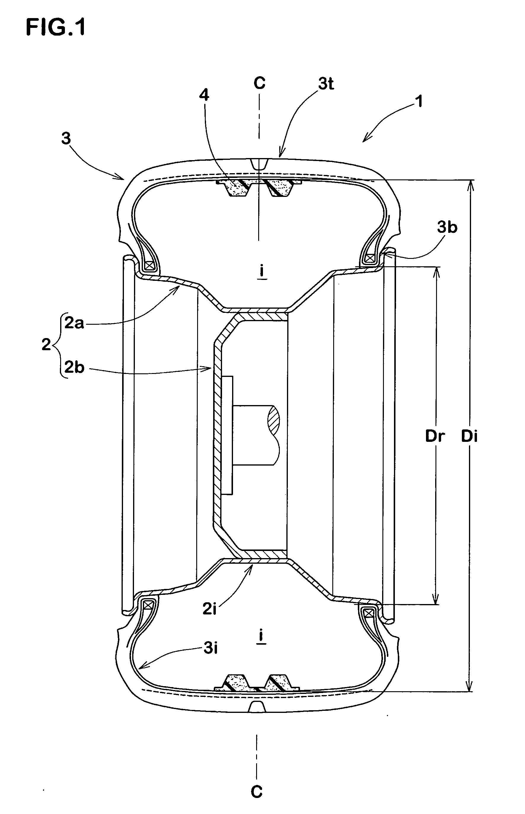
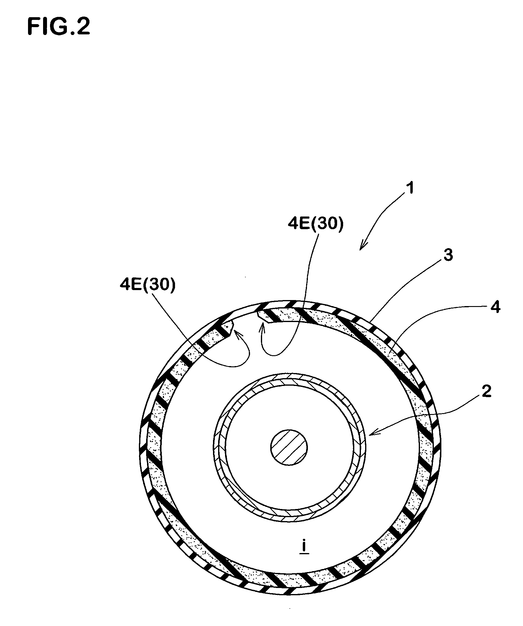
A pneumatic tire and rim assembly is provided in the cavity with a noise damper in which a sponge material extending in a circumferential direction of the tire and having a volume v2 of 0.4 to 20% of entire volume v1 of the cavity, wherein the noise damper comprises a fixing surface fixed to a surface which surrounds the tire cavity, and a free surface directed to the tire cavity, a maximum value of thickness from the fixing surface to the free surface is in a range of 5 to 50 mm, including a thick mountain portion and a thin valley portion; and at least one of outer ends of the noise damper in the circumferential direction of the tire is formed into an inclined surface portion comprising a first inclined surface rising from the fixing surface and a second inclined surface extending from, the first inclined surface to the free surface.
Description
TITLE OF THE INVENTION [0001] Assembly of Pneumatic tire and Rim BACKGROUND OF THE INVENTION [0002] The present invention relates to an assembly of a pneumatic tire and a rim in which a noise damper made of sponge material is disposed in a tire cavity, thereby reducing a road noise during running. [0003] To reduce a road noise during running, Japanese Examined Patent Application Publication No. 3612059 and Japanese Published Patent Application No. 2005-138760 propose to dispose a noise damper comprising a long band-like sponge material extending in a circumferential direction of a tire in a tire cavity. Thereby, energy of resonance vibration of air (cavity resonance) of air generated in the tire cavity can be absorbed and moderated by the noise damper. [0004] The noise damper is formed by fixing a bottom surface of the noise damper to a cavity surface on the side of the tire or on the side of the rim. This prevents the noise damper from moving in the tire cavity and rubbing against ...
Claims
Application Information
Patent Timeline
Application Date:The date an application was filed.
Publication Date:The date a patent or application was officially published.
First Publication Date:The earliest publication date of a patent with the same application number.
Issue Date:Publication date of the patent grant document.
PCT Entry Date:The Entry date of PCT National Phase.
Estimated Expiry Date:The statutory expiry date of a patent right according to the Patent Law, and it is the longest term of protection that the patent right can achieve without the termination of the patent right due to other reasons(Term extension factor has been taken into account ).
Invalid Date:Actual expiry date is based on effective date or publication date of legal transaction data of invalid patent.

