Eureka AIR delivers breakthrough ideas for toughest innovation challenges, trusted by R&D personnel around the world.

Actuator

Inactive Publication Date: 2007-06-14
RIGAKU CORP
View PDF7 Cites 3 Cited by
  • Summary
  • Abstract
  • Description
  • Claims
  • Application Information

AI Technical Summary

Benefits of technology

[0008] By disposing the stators at the outside of the case, the inside of the case is not affected by the discharge gas from the laminated steel plates even when the core constituting the stator is formed of laminated steel plates, and thus the inside of the case can be kept to the high vacuum atmosphere.
[0031] As described above, according to the present invention, the high vacuum atmosphere can be formed in the case, and also sufficient durability and corrosion resistance can be held under high temperature or the severely temperature-varying environment.

Problems solved by technology

However, when the stators are merely disposed at the outside of the case, the interval between each stator and the rotor is increased, thus the magnetic force required for driving the rotor is weakened and there is a risk that sufficient torque cannot be achieved.

Method used


Image

  • Actuator
  • Actuator
  • Actuator

Examples


Embodiment Construction

[0039] Preferred embodiments of the present invention will be described with reference to the drawings.

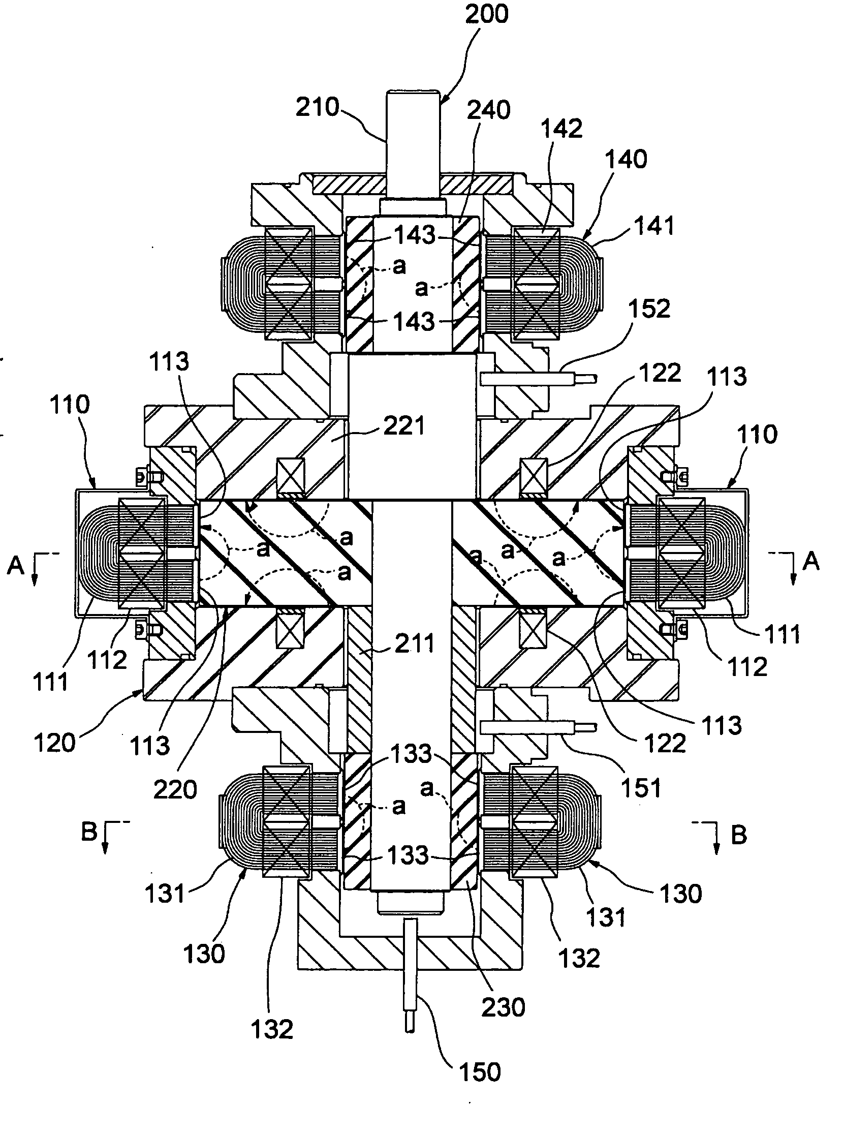
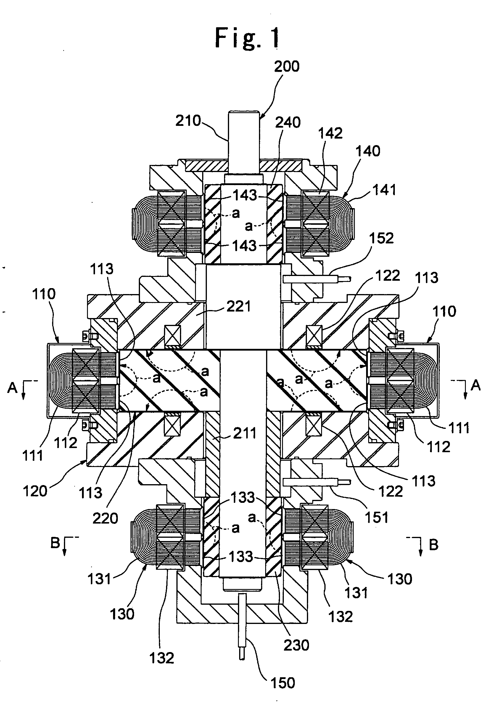
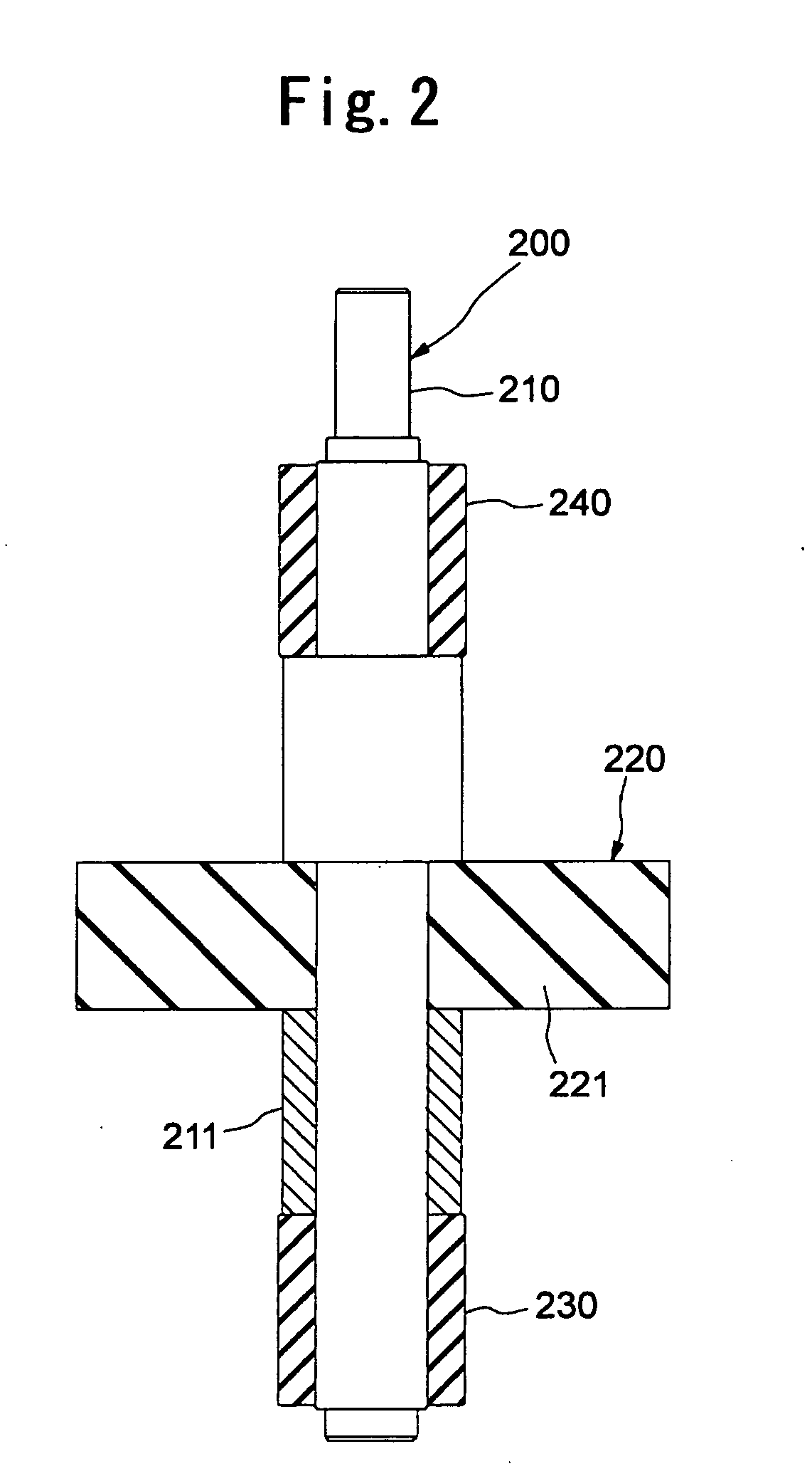
[0040]FIG. 1 is a cross-sectional front view showing an embodiment in which the present invention is applied to a rotary type motor device. FIGS. 2 and 3 are diagrams showing the constituent elements of the motor device shown in FIG. 1, and FIG. 2 is a partially cross-sectional front view showing the construction of the rotor. FIG. 3 is a cross-sectional front view showing a case and parts mounted there.

[0041] The motor device shown in these figures is equipped with a construction suitable to a vacuum motor operated under high temperature.

[0042] The motor device is equipped with a case 100, and a rotor 200 that is freely rotatably supported in the case 100.

[0043] As shown in FIG. 2, the rotor 200 is equipped with a round-bar type rotational shaft portion 210 formed of non-magnetic substance, and disc-shaped rotor portion 220 disposed substantially at the center. An annular firs...


PUM


Abstract

A case (100), a rotor (200) that is freely rotatably supported in the case (100), and stators (110) for rotating the rotor by magnetic force are provided. The stator (110) contains a core (111) mounted at the outside of the case (100), and a magnetic coil (112) wound around the core (111). An end face of the core (111) constituting a magnetic pole is formed of at least non-laminate ferromagnetic substance, and exposed to the inner surface of the case (100) so as to form a part of the inner wall of the case (100).

Description

TECHNICAL FIELD [0001] The present invention relates to an actuator having a mover freely movable in a case and stators for driving the mover by magnetic force, and particularly to an actuator suitably usable under high-vacuum or high-temperature environment. BACKGROUND ART [0002] A vacuum motor is known as an actuator used for a driving source such as a vacuum pump, a turbo molecular pump or the like. The vacuum motor is equipped with a rotor and a stator comprising an electromagnet for rotationally driving the rotor. As well known, the electromagnet is formed by winding a magnetic coil around a core. A laminate steel plate is used as the core constituting the electromagnet. The laminate steel plate is constructed by adhesively attaching plural thin steel plates to one another with resin adhesive agent. [0003] It is required for the vacuum motor to keep the inside of the case to a high-vacuum atmosphere. In the conventional vacuum motor, a rotor and a stator are disposed in the cas...

Claims


Application Information

Patent Timeline
IPC IPC(8): F01D1/36H02K7/09F04B17/00H02K1/14H02K1/18
CPCH02K1/148H02K1/185H02K7/09F16C32/04F16C2360/45
Inventor YAMAKATA, MASAAKIKOBAYASHI, YUJIAKIYAMA, KIYOSHI
Owner RIGAKU CORP
Why Eureka
Eureka Blog
Learn More