Weapon sight

Inactive Publication Date: 2007-06-21
CONESCU PAUL
View PDF25 Cites 52 Cited by
  • Summary
  • Abstract
  • Description
  • Claims
  • Application Information

AI Technical Summary

Benefits of technology

[0013] The invention provides an improved weapon sight that may be either integrated into a firearm or removably attached

Problems solved by technology

This type of system requires the shooter to obtain the actual distance to the target by other means and will not allow for ongoing, interactive adjustments of the sight or weapon.
Wh

Method used


Image

  • Weapon sight
  • Weapon sight
  • Weapon sight

Examples


Embodiment Construction

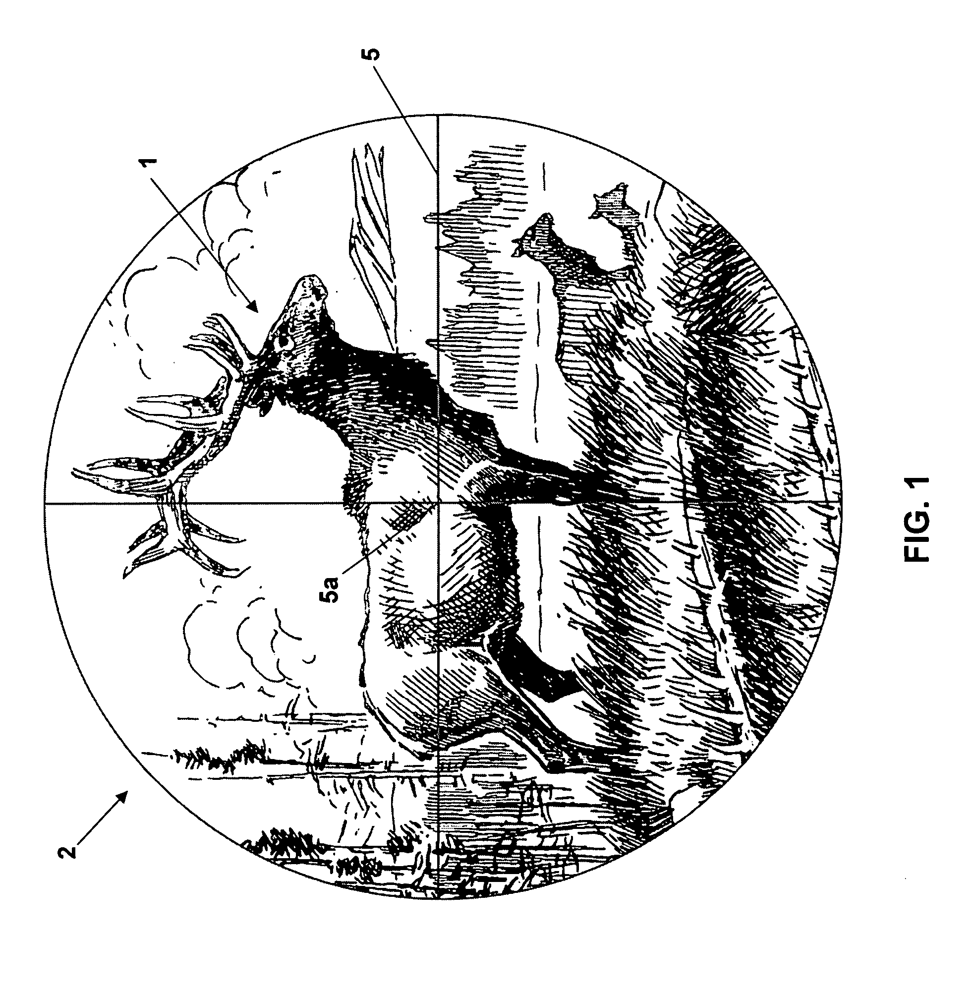
[0028] A typical, or unimproved, field of view 2 that is available in a standard telescope sight is shown in FIG. 1, wherein an intended target 1 (e.g., animal, human, fixed target, etc.) is visible, and often magnified. Typically a reticle 5 is also within the field of view 2 as an aiding instrument to the shooter. The reticle 5 aids the shooter in firing towards the intended target 1 by showing where the point of aim of the weapon 90 will be. In FIG. 1 a standard cross-hair type reticle 5 is employed wherein the point of aim is shown at point 5a (i.e., where the cross-hairs intersect) for a predetermined distance to the target (e.g., 200 feet to intended target). If a distance computing laser is additionally used on the weapon, the reticle 5 additionally may show the focal point of the distance computing laser 5a. With the field of view 2 with the standard telescopic sight, the shooter cannot accurately discern how far to move the intersection of the crosshairs 5a (via moving the ...


PUM


Abstract

The invention includes a sighting system for use with a firearm that has a telescopic sight, a laser rangefinder for providing the distance to the target, device(s) for receiving various inputs, a computing system that calculates the point of aim of the firearm's projectile based upon the input(s) and the calculated distance to the target, and a display means that provides an image of the computed point of aim within the telescopic sight's field of view. A method and weapon that employs the sighting system is disclosed.

Description

BACKGROUND OF THE INVENTION [0001] 1. Technical Field [0002] The invention relates generally to a weapon sighting device to be attached to or integrated with a rifle or handgun, and more specifically, to a weapon sight and sighting system that improves the accuracy of the firing of a rifle or handgun by providing an improved anticipated point of impact of the projectile. [0003] 2. Background Art [0004] In the art of firearm sights and sighting systems there are various products available that aid the shooter with viewing an intended target and informing the shooter as to the anticipated point of impact on the target of the projectile, or round. Several parameters influence the trajectory of the projectile, ultimately altering the trajectory of the round so that the actual point of impact differs from the anticipated point of impact. As these sights and sighting systems improve in their incorporation and compensation for these numerous parameters, the difference between the anticipat...

Claims


Application Information

Patent Timeline
IPC IPC(8): F41G1/00
CPCF41G1/473F41G3/06F41G3/08
Inventor CONESCU, PAUL
Owner CONESCU PAUL
Why Eureka
Try Eureka