System and method for determining whether a locomotive or rail engine is coupled to a rail car or other engine

a technology for locomotives and rail engines, applied in the field of rail yards, can solve the problems of limiting the knowledge of rolling stock whereabouts to at most, inefficient operator-monitored systems, and complex operation of the entire rail yard

Inactive Publication Date: 2007-06-28
GENERAL ELECTRIC CO
View PDF6 Cites 48 Cited by
  • Summary
  • Abstract
  • Description
  • Claims
  • Application Information

AI Technical Summary

Benefits of technology

[0014] In another exemplary embodiment, a method for determining whether a coupler of a locomotive engine is in either a coupled or uncoupled state is also provided. The method comprising: providing a signal indicative of the state of the coupler, the signal being provided a sensor configured to provide the signal as the coupled state of the coupler has changed; transmitting the signal wirelessly to a controller; processing the signal with a control algorithm resident upon the controller; and providing visually perceivable indication of the position of the coupler.

Problems solved by technology

The various services in a rail yard compete for resources such as personnel, equipment, and space in various facilities so that managing the entire rail yard efficiently is a complex operation.
For example, automated equipment identification (AEI) readers and AEI computers determine the location of rolling stock at points in the sequence of operations, but in general, this information limits knowledge of rolling stock whereabouts to at most, the moment at which the rolling stock arrived, the moment at which the rolling stock passes the AEI reader, and the moment at which the rolling stock departs.
However, an operator-monitored system can be inefficient in that it does not result in real time monitoring of the train engine's status as such communication, if present, may be exchanged well after the coupling or uncoupling event has occurred.

Method used


Image

  • System and method for determining whether a locomotive or rail engine is coupled to a rail car or other engine
  • System and method for determining whether a locomotive or rail engine is coupled to a rail car or other engine
  • System and method for determining whether a locomotive or rail engine is coupled to a rail car or other engine

Examples


Embodiment Construction

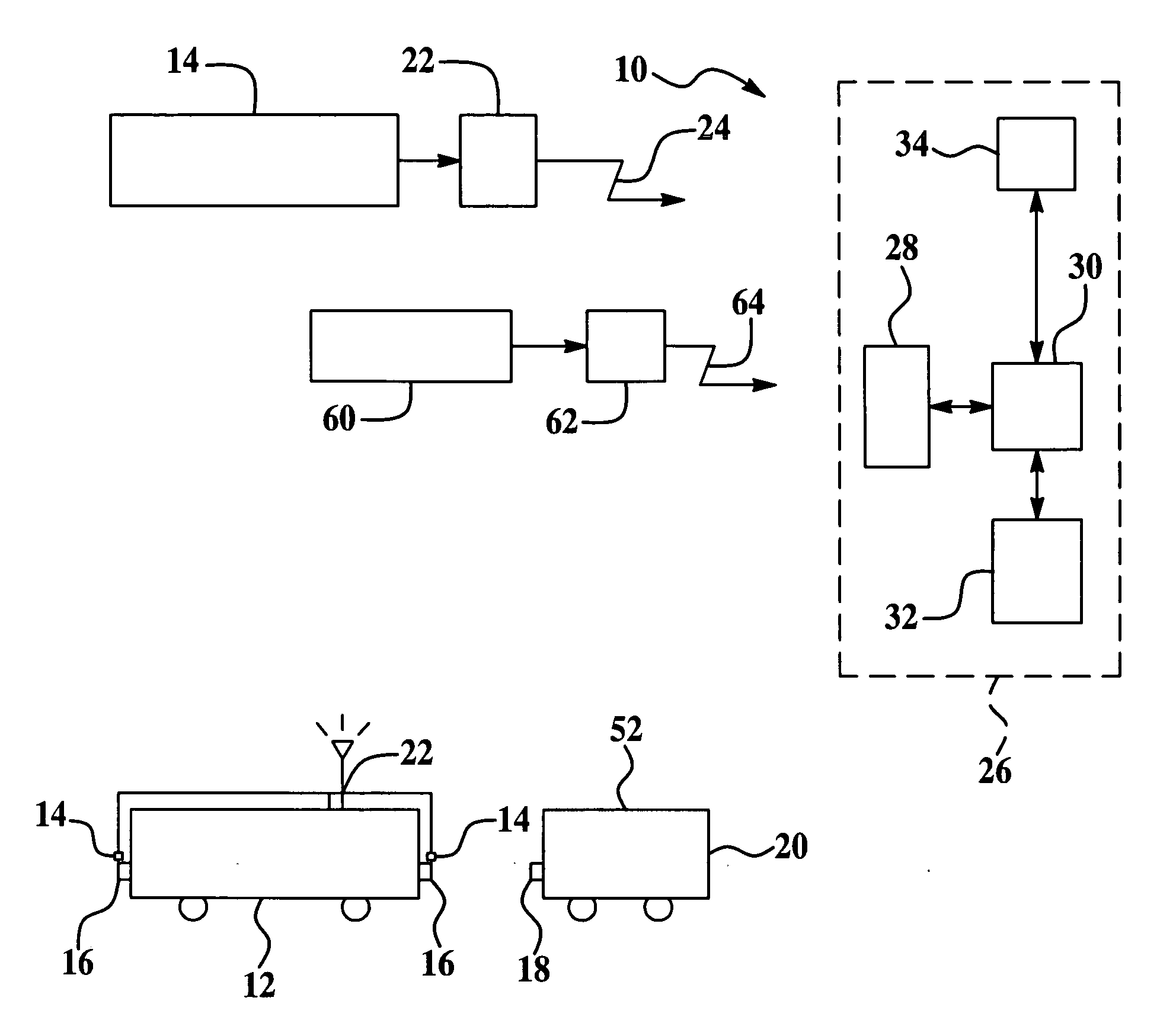
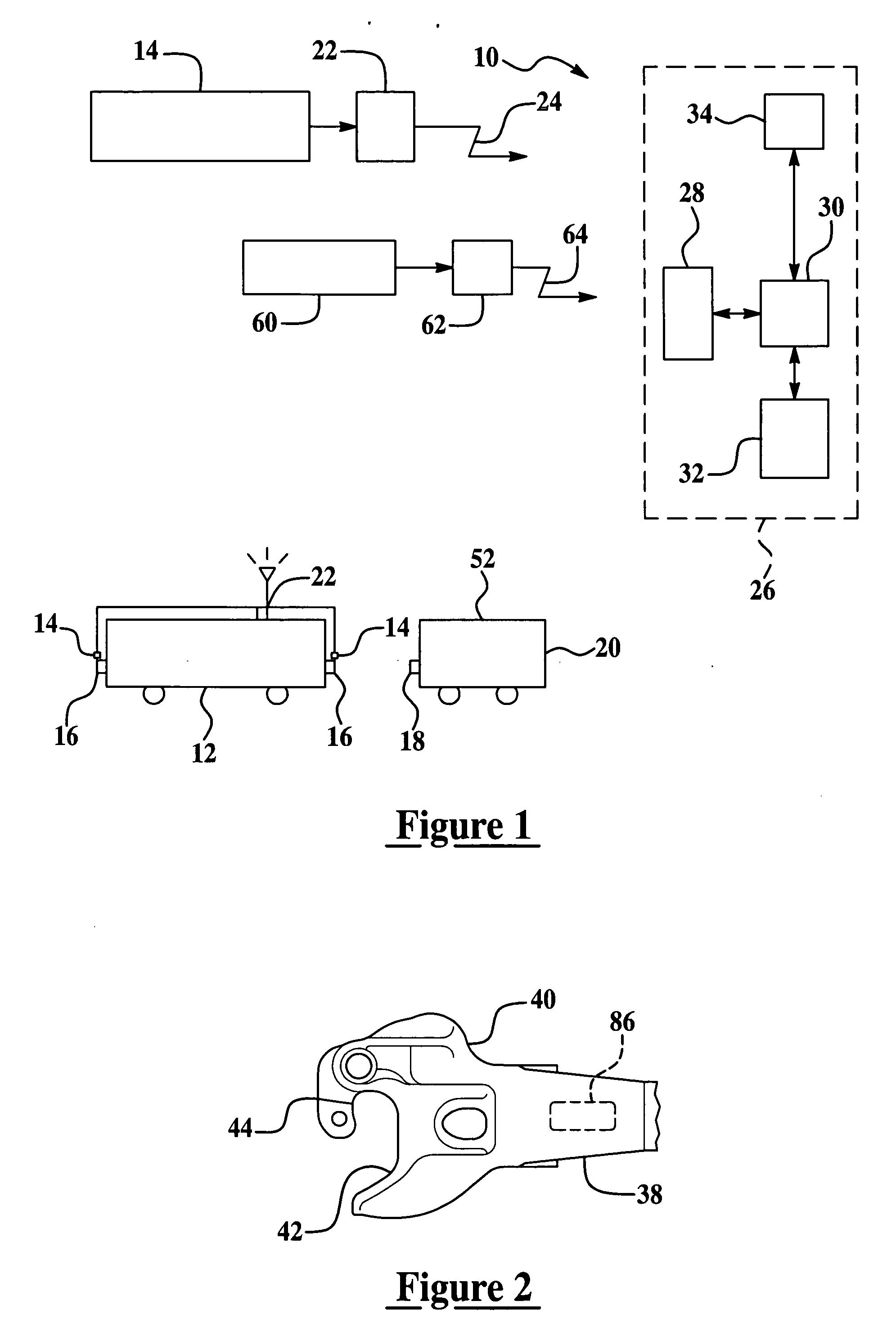
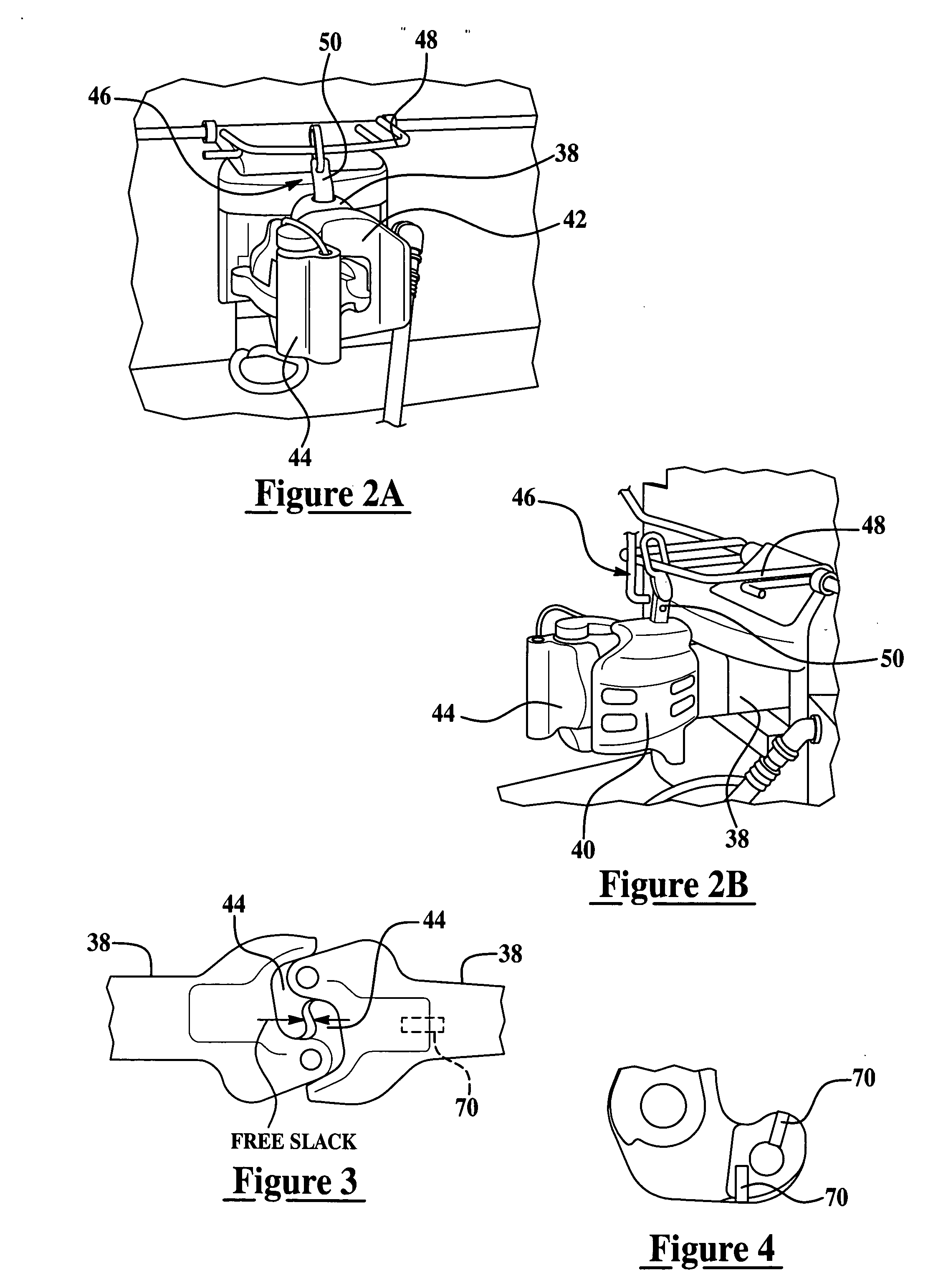
[0024] Exemplary embodiments of the present invention are directed to a system and method for robust determination of a locomotive's coupler status. In general, yard engines or locomotives are dedicated to moving road locomotives or other rail cars (e.g., cars that are pushed or pulled by locomotives) to and from different service and staging areas of a rail yard. Accordingly, it is desirable to know when a yard engine is coupled to a rail car or road locomotive. In accordance with an exemplary embodiment, sensors are provided to determine both a coupled state and an uncoupled state of the locomotive. The sensor output is conveyed over a wireless network to a control and monitoring system. In one exemplary embodiment the coupler sensor data may be combined with other data such as speed and direction of motion of the locomotive, which can also be provided wirelessly. This information allows assessment and utilization of the locomotive. Furthermore, the coupler status can be used to m...


PUM


Abstract

An apparatus and method for indicating whether a coupler of a locomotive is in a coupled or uncoupled state is provided. The apparatus comprising: a sensor positioned on a portion of the coupler, wherein the sensor provides a real-time signal indicative of either a coupled or an uncoupled state of a coupler, wherein the signal is transmitted wirelessly by a transmitter in operable communication with the sensor. The method comprising: providing a signal indicative of the presence or proximity of a second coupler to the first coupler, the signal being provided by a sensor configured to provide the signal as the state of the coupler has changed; transmitting the signal wirelessly to a controller; processing the signal with a control algorithm resident upon the controller; and providing visually perceivable indication of the position of the coupler.

Description

BACKGROUND [0001] This invention relates generally to rail yards, and more particularly to methods and apparatus for determining whether a train engine is coupled to a rail car. [0002] Rail yards are the hubs of railroad transportation systems. Therefore, rail yards perform many services, for example, freight origination, interchange and termination, locomotive storage and maintenance, assembly and inspection of new trains, servicing of trains running through the facility, inspection and maintenance of railcars, and railcar storage. The various services in a rail yard compete for resources such as personnel, equipment, and space in various facilities so that managing the entire rail yard efficiently is a complex operation. [0003] The railroads in general recognize that yard management tasks would benefit from the use of management tools based on optimization principles. Such tools use a current yard status and a list of tasks to be accomplished to determine an optimum order in which...

Claims


Application Information

Patent Timeline
Patent Type & Authority Applications(United States)
IPC IPC(8): B61L23/00
CPCB61G7/14B61J3/00B61L15/0054B61L15/02
Inventor DAVENPORT, DAVID MICHAELBHOTIKA, RAHULHERSHEY, JOHN ERIKMITCHELL, ROBERT JAMESANDARAWIS, EMAD ANDARAWISWELLES, KENNETH BRAKELEY
Owner GENERAL ELECTRIC CO
Why Eureka
Try Eureka