Power management lock system and method

a technology of power management and lock system, which is applied in the field of power management of electronic lock system, can solve the problems of insufficient power management of traditional electronic door locks of the type typically used in hotel guest rooms, insufficient power management of lock power consumption, and insufficient power management of storage devices disposed in door locks that have been charged by inductive power transfer

Active Publication Date: 2007-06-28
INNCOM INT INC
View PDF13 Cites 91 Cited by
  • Summary
  • Abstract
  • Description
  • Claims
  • Application Information

AI Technical Summary

Benefits of technology

The invention is a power management lock system that includes a power signal generator, an electronic lock unit, and an energy storage device. The power signal generator generates a wireless power signal that is transmitted to the energy storage device to power the electronic lock unit. The system also includes a plunger that senses the open or closed condition of the door and a power sensor that detects the presence and strength of the wireless power signal. The control assembly of the electronic lock unit receives data from the plunger and operates in an open power save mode when the door is in the open condition. The power sensor transmits power data to the control assembly when the door is in the closed position. The control assembly receives power from the energy storage device. The method also includes sensing the open condition of the door and transmitting the data to the control assembly, which disables the electronic lock unit. The technical effect of this invention is to manage power consumption in electronic lock systems by controlling the power signal based on the open or closed condition of the door.

Problems solved by technology

The technical problem addressed in this patent text is the inefficient power consumption of traditional electronic door locks used in hotels, which can lead to a quickly depleted battery and a non-functioning lock. The patent aims to develop power management strategies that take into account the power needs of open and closed conditions, to avoid the need for more powerful batteries and reduce expense for hotels.

Method used


Image

  • Power management lock system and method
  • Power management lock system and method
  • Power management lock system and method

Examples


Embodiment Construction

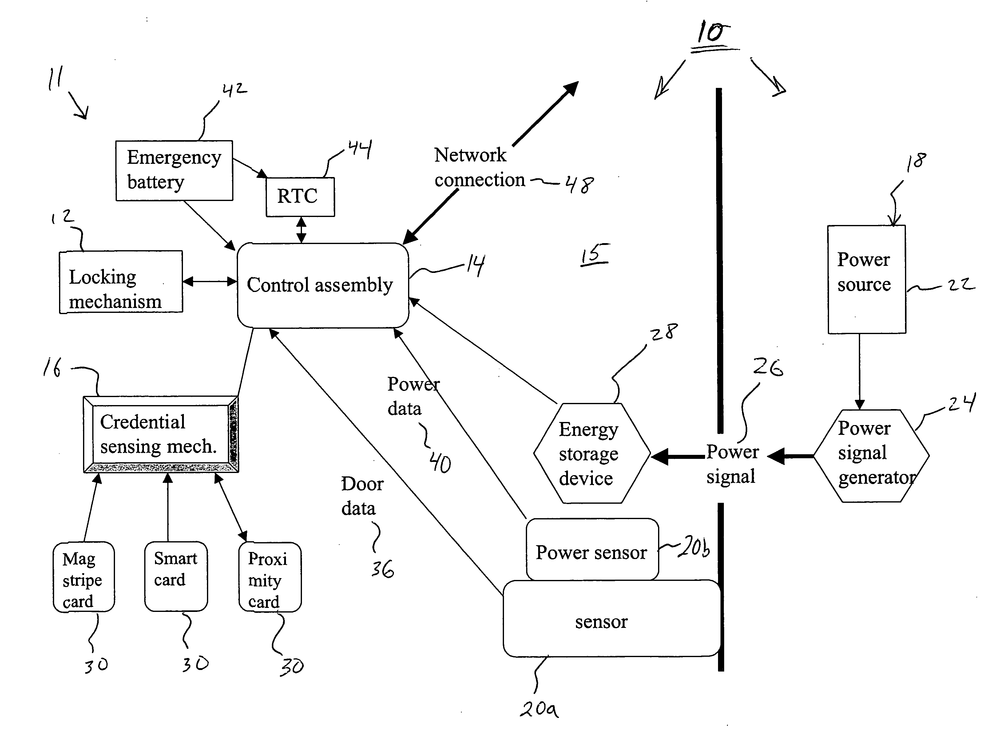
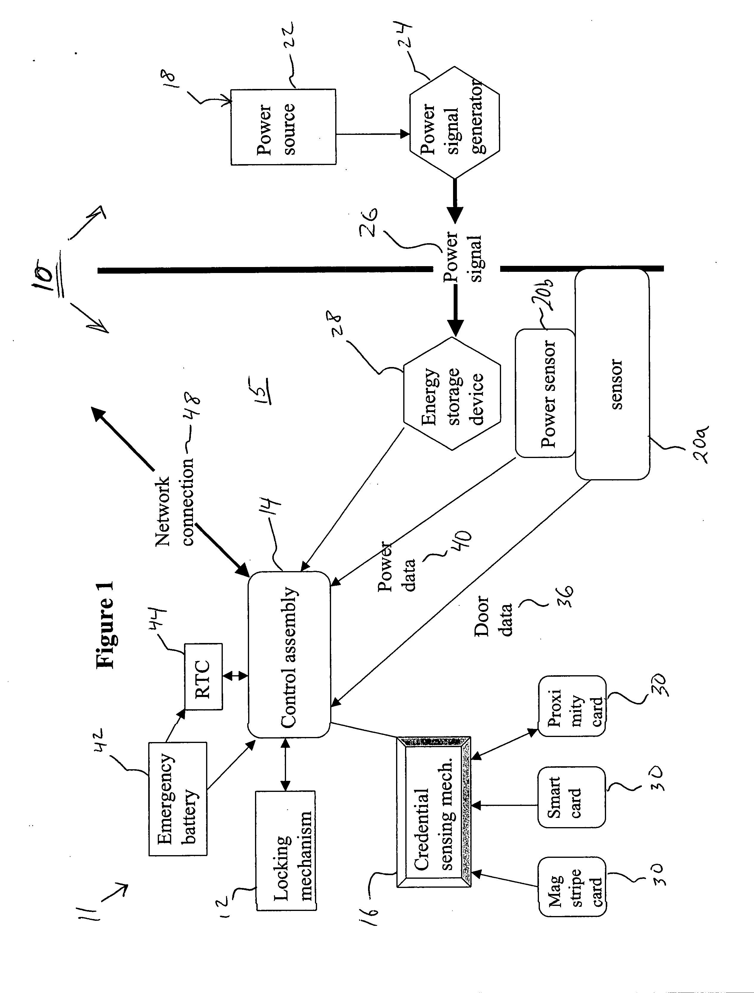
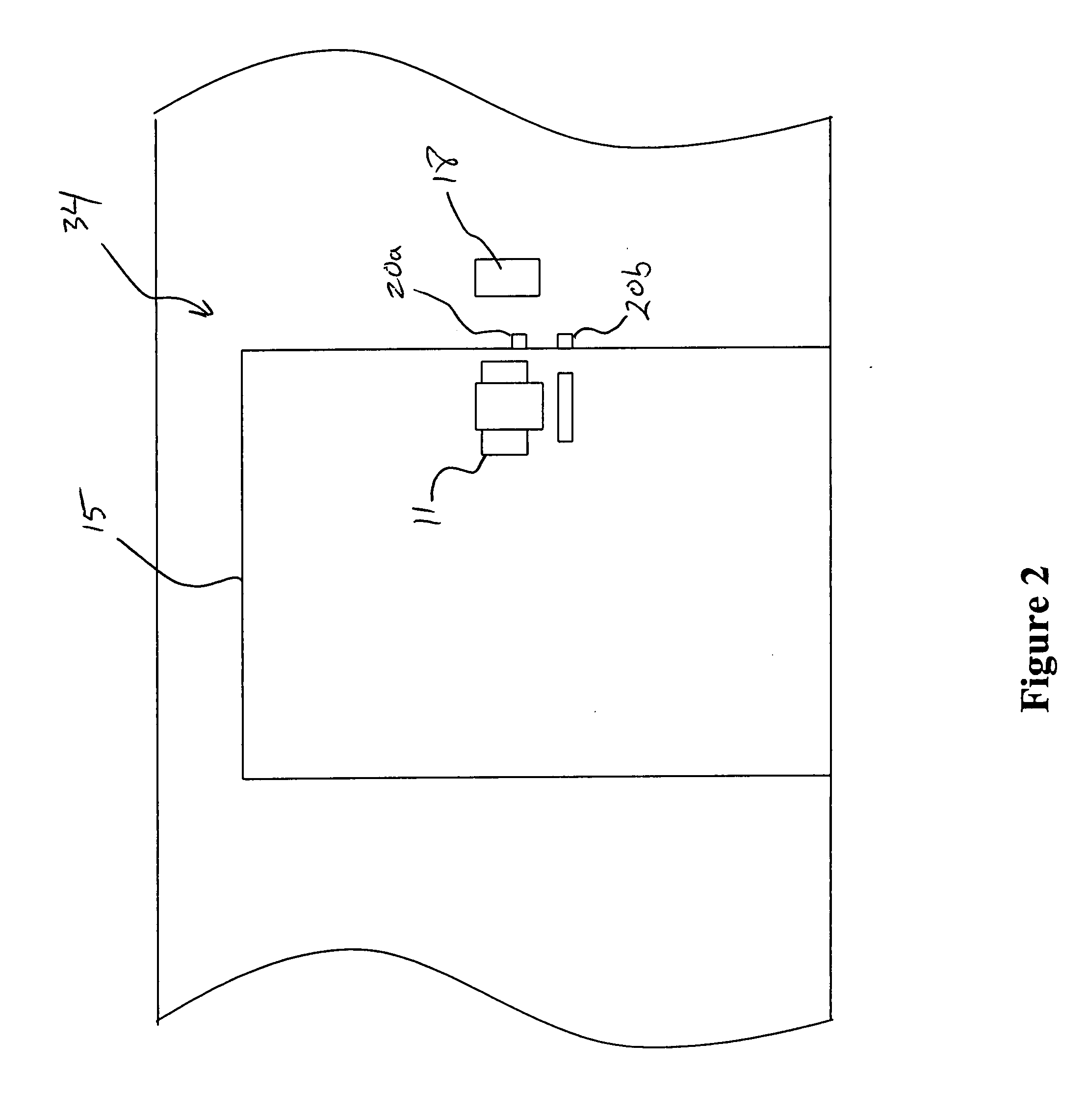
[0015]FIGS. 1-2 show an exemplary power management electronic lock system 10 in accordance with an embodiment of the invention. The system 10 includes an electronic lock unit 11 disposed in a door 15 and a power generating system 18 disposed external to the door 15. The electronic lock unit 11 comprises, among other elements, a locking mechanism 12, a corresponding lock control assembly 14, a credential sensing mechanism 16, at least one sensor 20a, 20b, and an energy storage device 28. The power generating system 18 generally includes a power source 22 and a power signal generator 24.

[0016] Generally, the electronic lock unit 11 and / or the power generating system 18, in one embodiment of the invention, are similar to that disclosed in U.S. patent application Ser. Nos. 11 / 082,559 and 11 / 082,577, both filed on Mar. 17, 2005, the entire contents of both said applications is incorporated by reference herein.

[0017] As will be discussed herein at length, the control assembly 14, which ...


PUM


Abstract

A power management lock system including an electronic lock unit configured to lock and unlock a door and further including at least one sensor in communication with the electronic lock unit, the sensor configured to sense an open condition of the door and a closed condition of the door, wherein the electronic lock unit is configured to receive door data pertaining to the open condition and the closed condition from the at least one sensor, and where the electronic lock unit is further configured to manage the provision of power within the electronic unit based upon the door data.

Description


Claims


Application Information

Patent Timeline
Owner INNCOM INT INC
Why Eureka
Try Eureka