
Transmit power allocation in a distributed MIMO system

a technology of transmit power and distributed mimo, which is applied in the direction of transmission monitoring, power management, wireless communication, etc., to achieve the effect of increasing maximising the equal throughput ra

Active Publication Date: 2007-06-28
APPLE INC
View PDF13 Cites 52 Cited by
  • Summary
  • Abstract
  • Description
  • Claims
  • Application Information

AI Technical Summary

Benefits of technology

The invention is about using a cellular wireless system with distributed MIMO channels to improve communication between a base station and a mobile terminal. The system uses spatial modes of the wireless channel for communication between the base station and the mobile terminal, and simultaneously employs these modes for communication with other mobile terminals in the coverage area. The transmitter power is allocated between the spatial modes of each distributed MIMO channel to maximize the equal throughput rate within the coverage area. This results in higher throughput rates and supports a greater number of mobile terminals without the coverage penalty associated with water-pouring. The invention provides methods for allocating power and a base station for both distributed MIMO and SDMA cellular radio systems. The technical effects of the invention include improved communication quality and higher throughput rates for mobile terminals.

Problems solved by technology

If it were to be employed in a system where, for example, each mode of the channel were to be used to support communication with a different mobile terminal, then those mobile terminals reliant upon modes with no power allocation would find themselves effectively outside the coverage of the base station, which typically is undesirable.

Method used


Image

  • Transmit power allocation in a distributed MIMO system
  • Transmit power allocation in a distributed MIMO system
  • Transmit power allocation in a distributed MIMO system

Examples


Embodiment Construction

[0023] As discussed above, in a distributed MIMO system there are several possible ways of servicing the mobile stations in a cell (i.e. that group of mobile stations being serviced by the same set of base station antennas). Effectively, there are three main degrees of freedom. Firstly, the duration (or dwell) of transmissions to any one mobile station may be varied to increase or decrease the volume of data transmitted to that terminal. Thus more time slots may be allocated to a particular mobile station to increase the volume of data transmitted to that mobile station (for a given data rate). However, since the total transmission time is a finite resource, increased dwell for one mobile station will result in reduced dwell for other mobile stations sharing the same cell.

[0024] Secondly, the modulation level may be varied. Higher levels of modulation generally result in higher data rates (i.e. more data transmitted over a given period of time). However, the capability to increase ...


PUM


Abstract

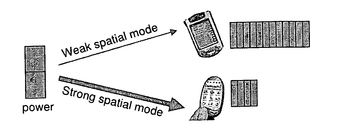
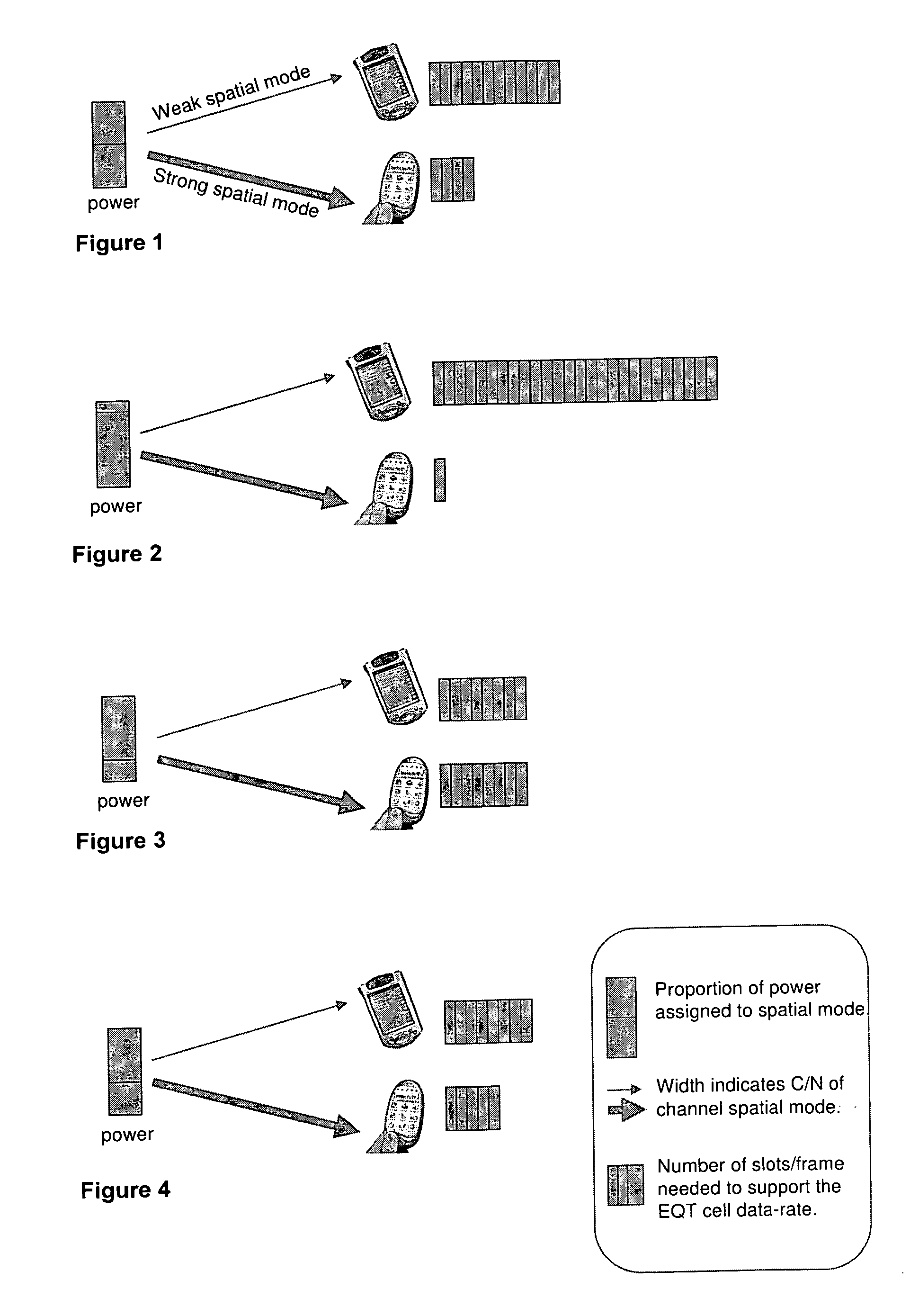
Allocate power so as to maximise the throughput of each user of a multi-user MIMO group, with the constraint that over time all users in the group have equal throughput. This differs from equal capacity per slot in that each user may be assigned multiple slots as well as unequal power. This is illustrated in FIG. 4. Total throughput is maximised on any given slot for any two users. Power is shared between the spatial modes such that the total number of slots used by the two users is minimised. The membership of the MIMO group may change between slots and thus throughput is not necessarily equalised on a slot by slot basis.

Description

BACKGROUND OF THE INVENTION [0001] 1. Field of the Invention [0002] This invention relates to the allocation of transmit power in the downlink of a distributed MIMO cellular radio network to achieve generally equal throughput for each mobile terminal whilst generally maximizing throughput for the network. [0003] 2. Description of the Related Art [0004] It is often desirable to provide a service uniformly within the coverage area of a cellular wireless network, despite variations in propagation conditions experienced by users in different locations. Conventionally this may be achieved by a scheduling technique in which the base station of the network spends a greater proportion of time transmitting to users in areas of poor reception and compensates by using a higher level of modulation (and hence higher data rate) for users with better reception. [0005] This prior art technique is equally applicable to SISO (single input, single output) systems, in which a single spatial mode of the...

Claims


Application Information

Patent Timeline
Patent Type & Authority Applications(United States)
IPC IPC(8): H04B7/00H04Q7/20H04W52/42
CPCH04B7/0434H04B7/0697H04B17/382H04B17/336H04W52/42
Inventor NADEN, JAMES MARKWILSON, FIONA
Owner APPLE INC
Learn More