Fluid-control system
- Summary
- Abstract
- Description
- Claims
- Application Information
AI Technical Summary
Benefits of technology
Problems solved by technology
Method used
Image
Examples
Embodiment Construction
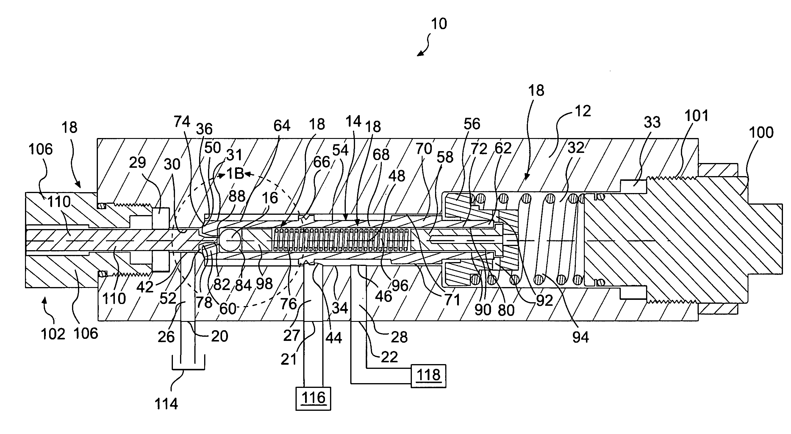
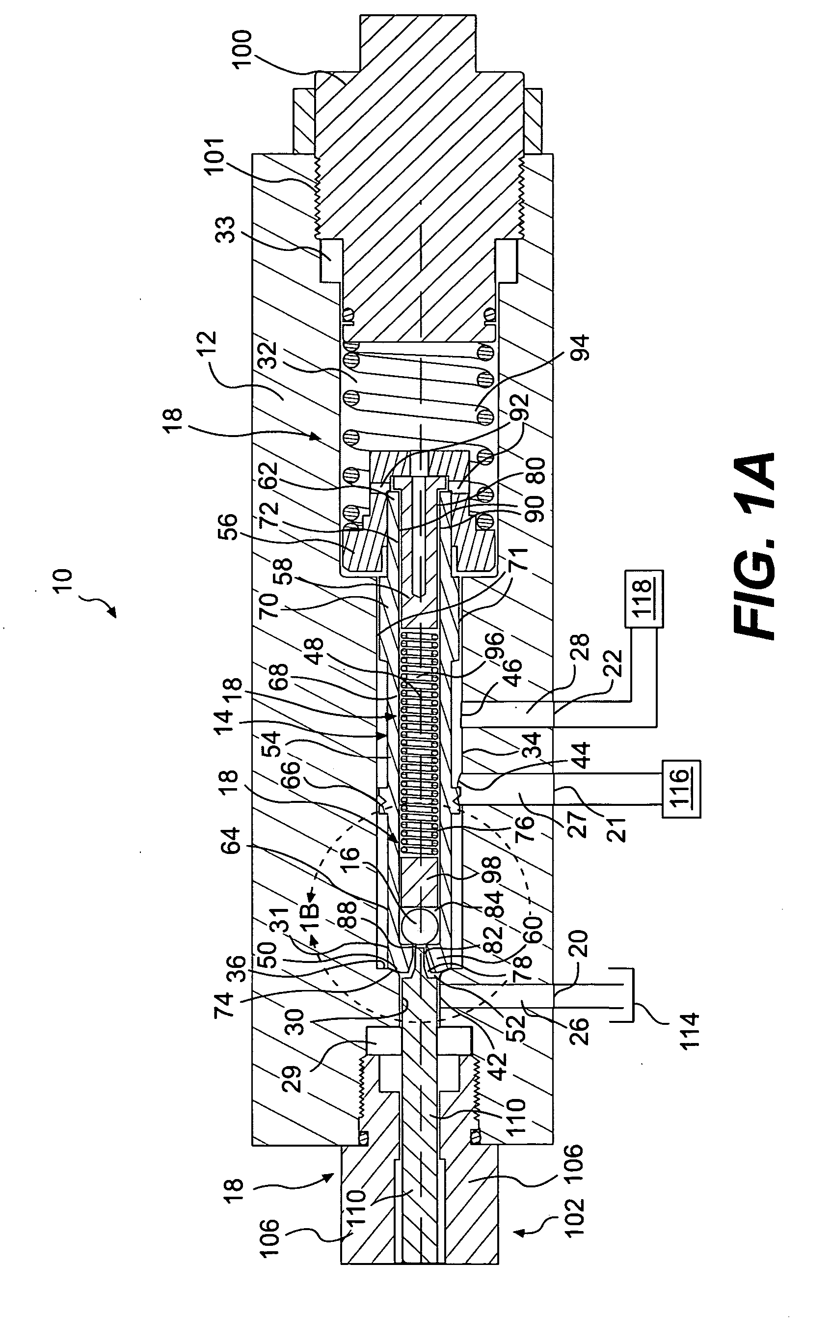
[0023]FIGS. 1A and 1B illustrate one embodiment of a fluid-control system 10 according to the present disclosure. As is shown in FIGS. 1A and 1B, fluid-control system 10 may be a valve, such as a spool valve. Fluid-control system 10 may include a valve housing 12, a first first valve element 14, a second valve element 16, and valve controls 18.
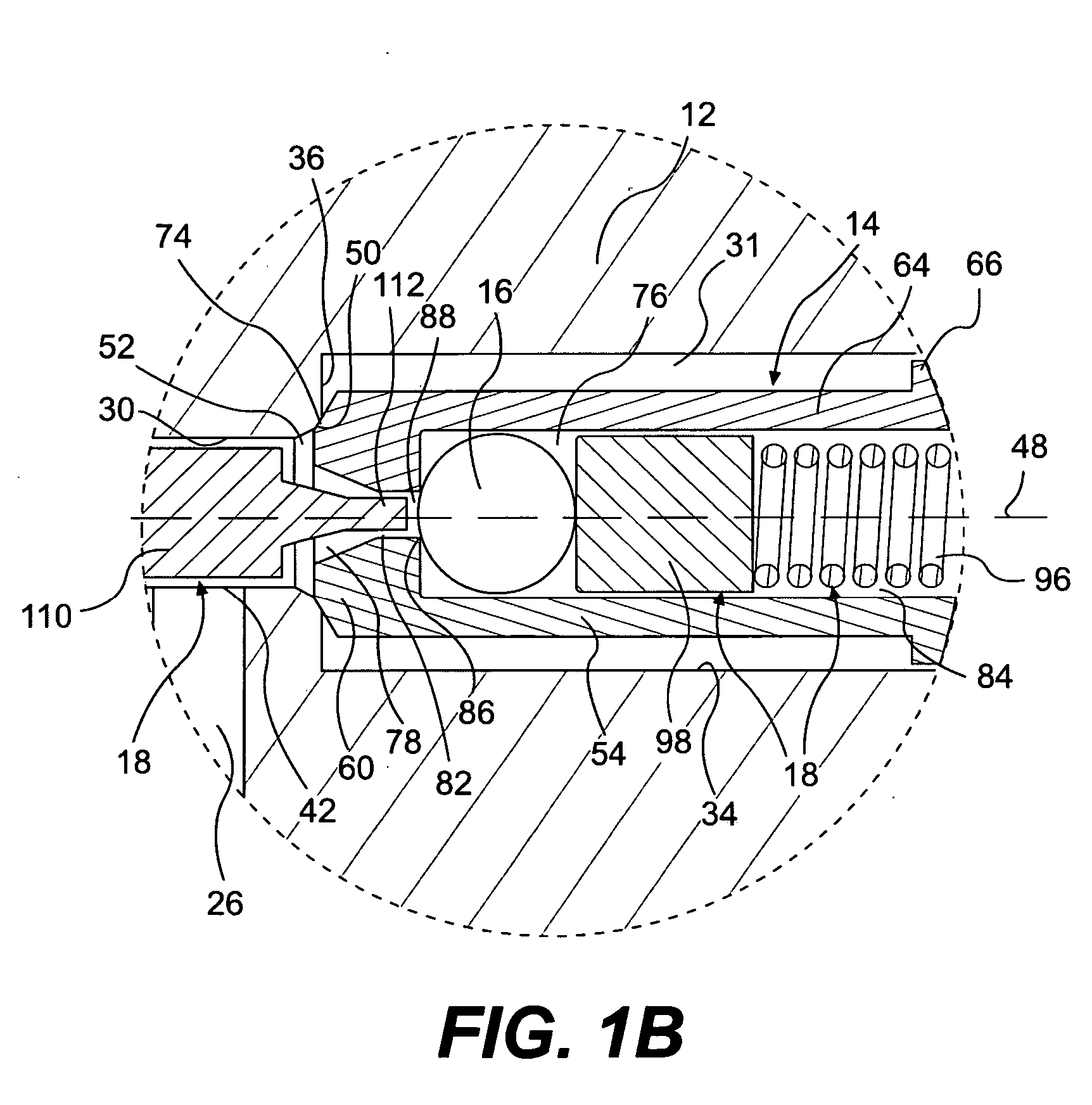
[0024] Valve housing 12 may include ports 20, 21, 22, passages 26, 27, 28, a cavity 29, a passage 30, and cavities 31, 32, 33. Cavity 31 may extend along an axis 48. As is shown in FIG. 1A, cavity 31 may have a substantially constant cross-section along axis 48. Passage 30 may extend from an opening 52 in an end wall 36 of cavity 31 to cavity 29. As is best shown in FIG. 1B, valve housing 12 may include a sealing surface 50 extending circumferentially around opening 52. Sealing surface 50 may taper outward as it extends toward cavity 31. Passage 26 may extend between port 20 and an opening 42 in the surface of passage 30. Similarly, passages ...
PUM
 Abstract
Description
Claims
Application Information
 - R&D
- Intellectual Property
- Life Sciences
- Materials
- Tech Scout
- Unparalleled Data Quality
- Higher Quality Content
- 60% Fewer Hallucinations
Browse by: Latest US Patents, China's latest patents, Technical Efficacy Thesaurus, Application Domain, Technology Topic, Popular Technical Reports.
© 2025 PatSnap. All rights reserved.Legal|Privacy policy|Modern Slavery Act Transparency Statement|Sitemap|About US| Contact US: help@patsnap.com


