Method and apparatus for surge pressure reduction in a tool with fluid motivator

a technology of motivator and surge pressure, which is applied in the direction of fluid removal, borehole/well accessories, construction, etc., can solve the problems of exasperated surge pressure, corresponding increase or surge in the pressure generated by fluids, and higher surge pressures

Inactive Publication Date: 2006-07-04
WEATHERFORD TECH HLDG LLC
View PDF11 Cites 32 Cited by
  • Summary
  • Abstract
  • Description
  • Claims
  • Application Information

AI Technical Summary

Benefits of technology

[0012]One embodiment provides for a downhole surge control tool defining an exhaust port for venting fluid. The tool comprises a body having (i) a first opening at a first end, (ii) a second opening at a second end and (iii) defining a bore traversing the tool to fluidly couple the first opening and the second opening; a wellbore fluid bypass path defined between the first opening and the exhaust port; and a fluid motivator to motivate fluid flow through the bypass fluid path and out through the exhaust port. In one embodiment, the fluid motivator may be a selected from a variety of devices including a Venturi jet comprising a nozzle, a mechanical pump (e.g., a centrifugal pump), and an electric pump. In a particular embodiment, the fluid motivator includes a first pump to provide a pressurized jet stream to a Venturi positioned proximate the bypass fluid path, whereby the Venturi produces a suction to motivate fluid flow from the first opening, through the bypass fluid path and out through the exhaust port.
[0013]Another embodiment provides a downhole surge control tool comprising a body having a first opening at a first end and a second opening at a second end and defining a bore traversing the tool to fluidly couple the first opening and the second opening. A valve is disposed in the bore and positionable in at least (i) a closed position to at least restrict fluid flow between the first opening and the second opening via the bore and (ii) an open position to allow fluid flow between the first opening and the second opening via the bore. A sealable fluid bypass path is defined between the first opening and an exhaust port formed in the body and a pump is oriented into at least a portion of the fluid bypass path.
[0014]Yet another embodiment provides a downhole surge control tool comprising a body having a first opening at a first end and a second opening at a second end and defining a bore traversing the tool to fluidly couple the first opening and the second opening. A valve is disposed in the bore and positionable in at least (i) a closed position to at least restrict fluid flow between the first opening and the second opening via the bore and (ii) an open position to allow fluid flow between the first opening and the second opening via the bore. A sealable fluid bypass path is defined between the first opening and an exhaust port formed in the body and a pump is oriented into at least a portion of the fluid bypass path A sealing member disposed in a cavity of the body is positionable in a closed position to seal the fluid bypass path and an open position to open the fluid bypass path. A collet sleeve is axially slidably disposed with respect to the body and comprises a plurality of collet fingers and one or more connecting members connecting the collet sleeve to the sealing member.
[0015]Still another embodiment provides a method of controlling surge pressure downhole, comprising providing a downhole surge control tool comprising a body defining a bore and a valve disposed in the bore and positionable in (i) a closed position to seal the bore and at least restrict fluid flow therethrough and (ii) an open position to unseal the bore. While the valve is in the closed position a motive fluid is flowed through a pump which operates to create a suction pressure. The suction pressure at least partially motivates flow of a wellbore fluid through a fluid bypass path formed in the surge control tool.

Problems solved by technology

One problem with running tools occurs when lowering a liner hanger, for example, at a relatively rapid speed in drilling fluid.
The rapid lowering of the liner hanger results in a corresponding increase or surge in the pressure generated by the fluids below the liner string.
The problems associated with surge pressure are exasperated when running tight clearance liners or other apparatus in the existing casing.
The reduced annular area in these tight clearance liner runs results in correspondingly higher surge pressures and heightened concerns over their resulting detrimental effects.
The surge pressure resulting from running a liner / casing into a wellbore has many detrimental effects.
Some of these detrimental effects include 1) lost volume of drilling fluid; 2) resultant weakening and / or fracturing of the formation when the surge pressure in the wellbore exceeds the formation fracture pressure, particularly in highly permeable formations; 3) loss of cement to the formation during the cementing of the liner in the wellbore due to the weakened and, possibly, fractured formations which result from the surge pressure on those formations; and 4) differential sticking of the drill string or liner being run into a formation during oil-well operations (that is, when the surge pressure in the wellbore is higher than the formation fracture pressure, the loss of drilling fluid to the formation allows the drill string or liner to be pulled against the permeable formation downhole, thereby causing the drill string or liner to “stick” to the permeable formation).
However, decreasing running speed increases the time required to complete the liner placement, resulting in a potentially substantial economic loss.
This approach is undesirable because the pressure drop through the drill pipe from the top of the liner / casing to the surface is significant, and the surge pressure below the liner / casing will still limit the run-in speed in many cases.
An additional drawback is that the fluid must then be returned to the wellbore by means of some pumping facility.
Further, even though the pressure is being relieved, the surge pressure still increases with increasing running speeds.

Method used


Image

  • Method and apparatus for surge pressure reduction in a tool with fluid motivator
  • Method and apparatus for surge pressure reduction in a tool with fluid motivator
  • Method and apparatus for surge pressure reduction in a tool with fluid motivator

Examples


Embodiment Construction

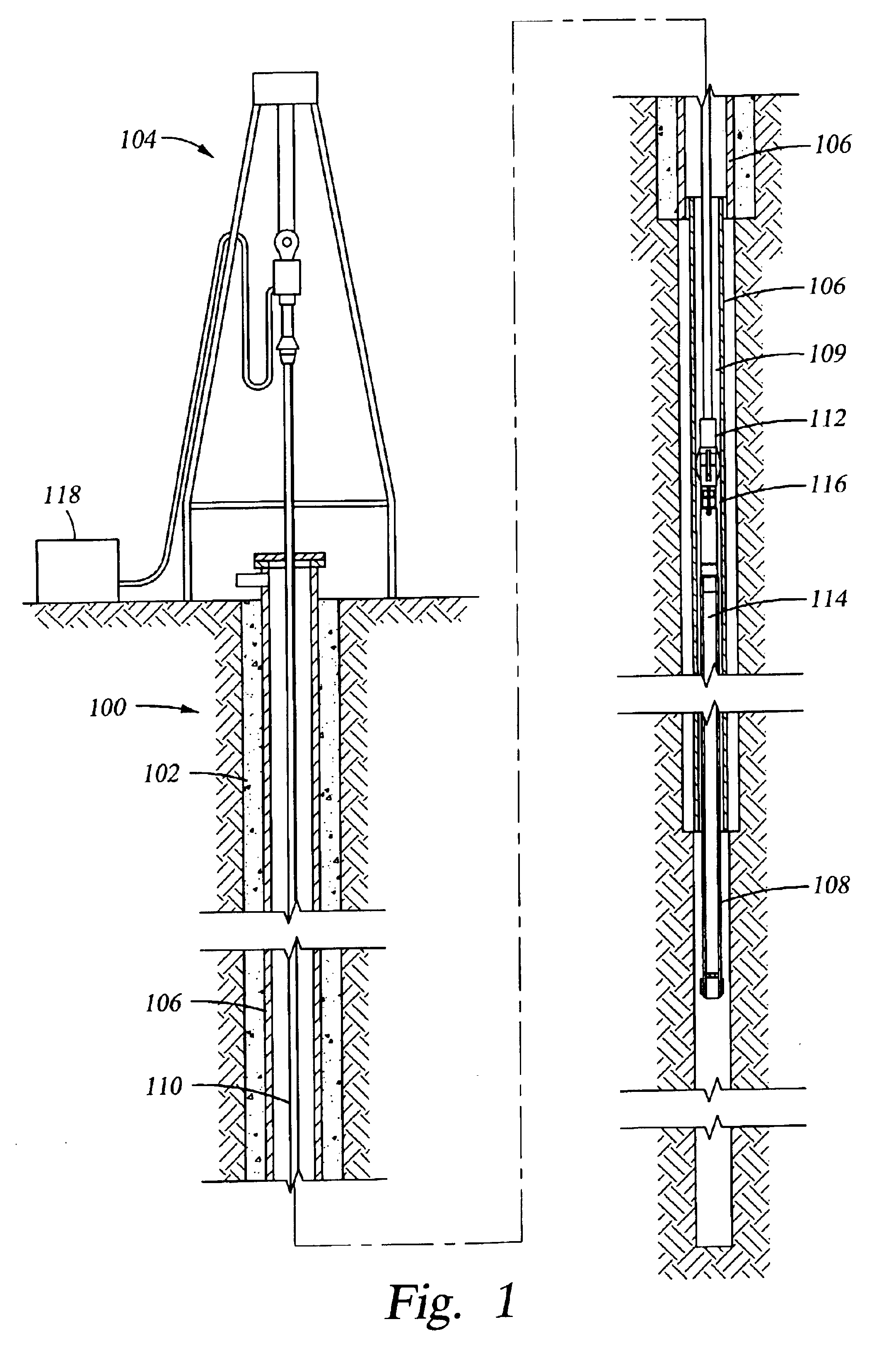
[0036]FIG. 1 is a cross-sectional view of a typical subterranean hydrocarbon well 100 which defines a vertical wellbore 102. In addition to the vertical wellbore 102, the well 100 may include a horizontal wellbore (not shown) to more completely and effectively reach formations bearing oil or other hydrocarbons. During or after formation of the wellbore 102, a series of liners are placed in therein to makeup the casing 106. The liners 108 (one shown) are lowered into the wellbore 102 by a working string 110, which is secured to a rig 104. In the present embodiment, the working string 110 includes a surge control tool 112 connected to a liner running tool 114. The liner running tool 114 carries the liner 108. The surge control tool 112 operates to reduce or substantially eliminate the presence of a surge pressure by motivating fluid flow from a central bore 109 of the liner 108, through the liner running tool 114, through the surge control tool 112 and into the annulus 116 formed betw...


PUM


Abstract

Apparatus and method for controlling pressure surges in a wellbore. One embodiment provides a downhole surge control tool equipped with a fluid motivator. The fluid motivator may be, for example, any type of motor or a venturi. The fluid motivator motivates wellbore fluid through a bypass channel formed in the tool and then out an exhaust port of the tool.

Description

BACKGROUND OF THE INVENTION[0001]1. Field of the Invention[0002]The present invention generally relates to an apparatus and a method for reducing downhole surge pressure, for example, while running a liner into a wellbore. More particularly, the invention relates to an apparatus and a method for reducing surge pressure by actively motivating fluid flow through a tool and into an annulus exterior to the tool.[0003]2. Description of the Related Art[0004]Running tools are used for various purposes during well drilling and completion operations. For example, a running tool is typically used to set a liner hanger in a well bore. The running tool is made up in the drill pipe or tubing string between the liner hanger and the drill pipe or tubing string running to the surface. In one aspect, the running tool serves as a link to transmit torque to the liner hanger to help place and secure the liner in the well bore. In addition, the tool also provides a conduit for fluids such as hydraulic f...

Claims


Application Information

Patent Timeline
Patent Type & Authority Patents(United States)
IPC IPC(8): E21B33/00E21B21/10E21B34/00E21B43/10
CPCE21B21/103E21B43/10E21B2034/002E21B2200/04E21B34/06
Inventor GUDMESTAD, TARALDMURRAY, MARK J.
Owner WEATHERFORD TECH HLDG LLC
Why Eureka
Try Eureka