
Method and a Device for in Situ Formation of a Seal in an Annulus in a Well

Active Publication Date: 2008-08-14
AGR CANNSEAL
View PDF9 Cites 27 Cited by
  • Summary
  • Abstract
  • Description
  • Claims
  • Application Information

AI Technical Summary

Benefits of technology

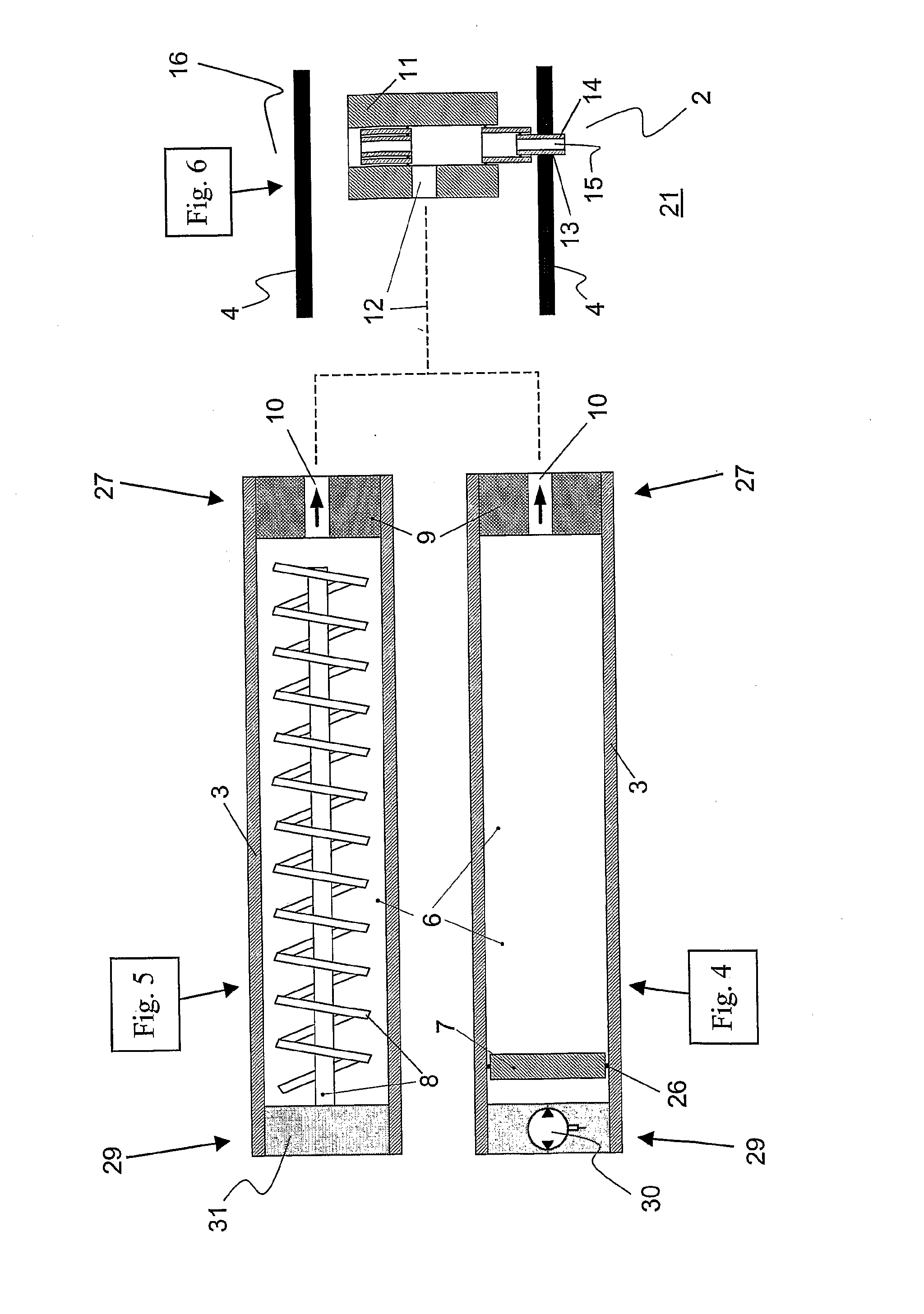
[0043]In one embodiment of this second variant of the method, at least a part of the solid-state packer material is heated and melted before the packer injection module is conveyed to said location vis-à-vis the annulus region. In so doing, the packer material is kept in a melted, liquid state in the packer chamber by means of said heating device. This is because some thermoplastic packer materials are available in granulate form and have high thermal insulation ability, thereby requiring a relatively large amount of energy and a long time to melt. It may therefore be advantageous to start the heating and melting before the packer injection module has been conveyed to the particular location in the well.
[0067]a coupling means for connecting the packer chamber in a flow-communicating manner to said hole through the pipe wall, thus rendering possible to conduct liquid packer material further into said annulus region.

Problems solved by technology

Arranging a completion string, for example, with external casing packers and / or gravel packs implies increased operational complexity and further completion costs for a well.
If no special zone isolation requirements are envisaged for a well, most likely the well will not be completed with gravel packs and / or extra external casing packers.
Prior art zone isolation thus lack the operational flexibility that is desirable during the well's operating phase after completion.
Even in the event that special zone isolation requirements are envisaged, and that further external casing packers therefore are mounted on the outside of the completion string, such casing packers may still have a non-optimum placement along the string relative to the zone isolation requirements that may arise after completion of the well.
It is not uncommon, however, to experience that the assumed isolation requirements do not agree with the actual isolation requirements that may arise in the well's operating phase.
An external casing packer, such as an inflatable casing packer, may also fail while being set or after being set in the well's annulus, whereby the annulus is sealed unsatisfactorily.
The casing packer may fail due to an erroneous setting function and / or setting procedure.
In an open well bore, it may also have an unsatisfactory sealing function if the geometric shape of the well's wall is enlarged beyond the outer dimension of the packer, such as in a washed out well bore.
Such an incomplete filling reduces the function and efficiency of the gravel pack in the well.
It has thus proven difficult to obtain injection liquids possessing optimum liquid characteristics both with respect to flow properties and setting properties.
In practice, non-optimum injection liquids therefore are used, in which one or more liquid properties are prioritised at the expense of other liquid properties.
This imbalance may, among other thing, lead to a undesirable and unfortunate mixing of different fluids in the annulus, which causes dilution and / or contamination of the annulus seal and also subsequent inadequate seal distribution and / or seal quality.
Said imbalance may also cause an unfavourable setting time for the injection liquid.
Yet further, a liquid injection process of this type also requires a thorough control of injection volume and placement of the injection liquid in the annulus, which may be difficult to carry out with sufficient precision to achieve a good result.
Inadequate control in this connection may also lead to unfavourable injection liquid contamination due to undesirable mixing with other fluids in the annulus, and / or it may have unfortunate effects on surrounding rocks.
Such a liquid injection process also implies increased operational complexity and further costs for a well, especially in connection with underwater operations offshore.
Although some features of the device according to U.S. Pat. No. 4,415,269 resemble those of the present invention, the device is not suitable for forming remedial annulus seals in a well.
This is because some thermoplastic packer materials are available in granulate form and have high thermal insulation ability, thereby requiring a relatively large amount of energy and a long time to melt.

Method used


Image

  • Method and a Device for in Situ Formation of a Seal in an Annulus in a Well
  • Method and a Device for in Situ Formation of a Seal in an Annulus in a Well
  • Method and a Device for in Situ Formation of a Seal in an Annulus in a Well

Examples


Embodiment Construction

OF EMBODIMENTS OF THE INVENTION

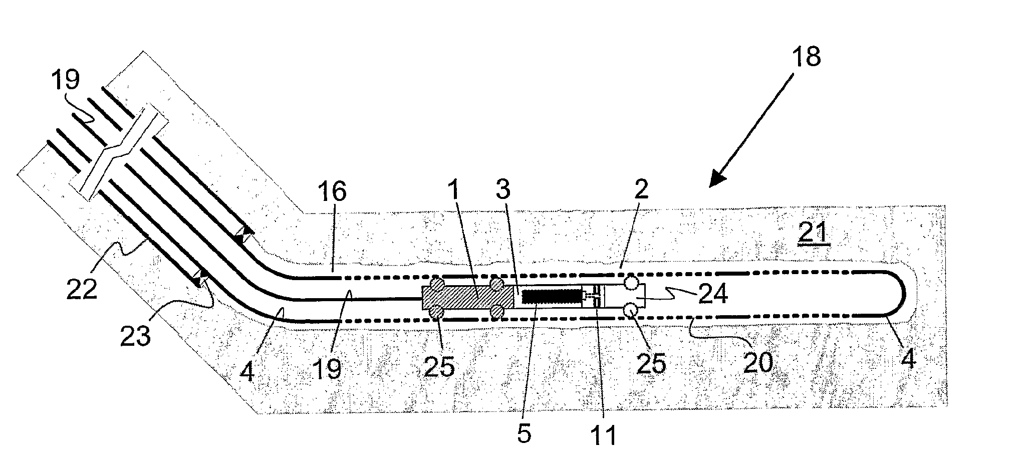
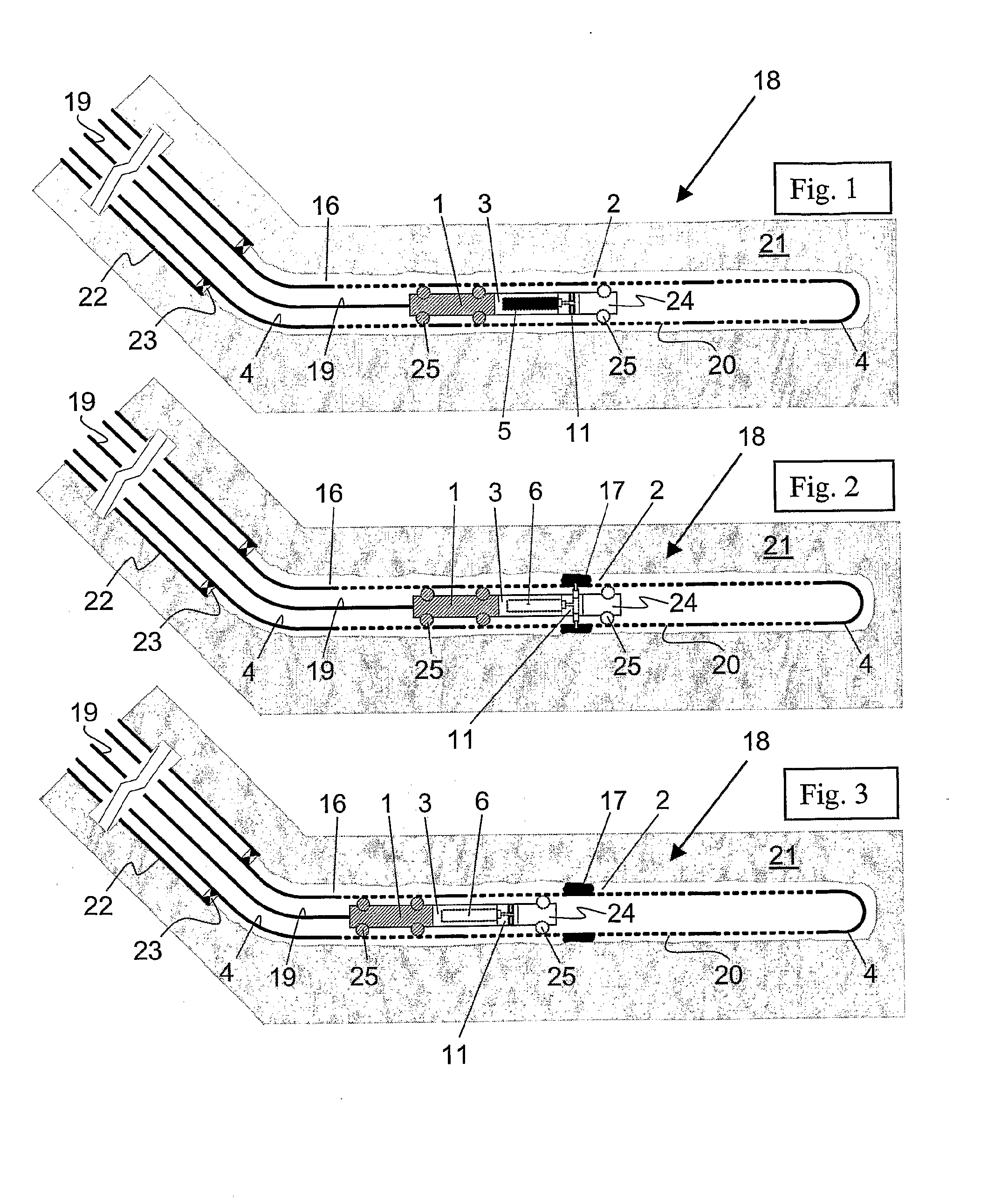
[0084]FIGS. 1-3 show a well tractor 1 located in a production tubing 4 through an open hole completed horizontal portion of a production well 18. Well tractors constitute prior art and are therefore not described in further detail herein. Along said horizontal portion, the production tubing 4 is provided with inflow openings 20 that, via an intermediate annulus 16, connect the production tubing 4 in a flow-communicating manner with permeable rocks in a surrounding reservoir 21. Above said horizontal portion, a casing 22 and a so-called guide shoe 23 at the bottom thereof surround the production tubing 4.

[0085]The uppermost side of the well tractor 1 is connected to surface via a connection line 19, which in this example is comprised of an electric cable. The electric cable 19 is arranged in a manner allowing it to transmit energy and control signals to both the well tractor 1 and a device according to the invention being connected to the lowermost side...


PUM


Abstract

A method and a device for in situ formation of a seal (17) in a region (2) of an annulus (18) located around a pipe structure (4) in a well (18), in which the method comprises the following steps: (A) to convey a perforation device into the pipe structure (4) to a location vis-a-vis said region (2) of the annulus (16); (B) by means of the perforation device, to make at least one hole (13) through the pipe wall of the pipe structure (4) at said annulus region (2); (C) to force a liquid sealing material, which is capable of entering into solid state, through said hole (13) and further into the annulus region (2) for the filling thereof, where-upon the sealing material enters into solid state and forms said seal (17). The distinctive characteristic of the method is that step (C) thereof also comprises:—to choose a fusible, solid-state packer material (5) as raw material for said seal material;—to heat and melt at least a part of the solid-state packer material (5); and—subsequently, to force liquid packer material (5) into the annulus region (2) via the at least one hole (13) through said pipe wall, whereupon the liquid packer material (5) enters into solid state and forms said seal (17) in the annulus region (2).

Description

FIELD OF INVENTION [0001]The invention concerns a method and a device for downhole formation of a pressure- and flow-preventive seal in an annulus of an underground well, for example a hydrocarbon well or an injection well. The invention involves technology within the field of remedial annulus seals or annulus packers for use in a well, and especially formation of such seals during the post-completion phase of a well, i.e. the phase when the well is already completed and is operational. Moreover, the invention advantageously may be used both in uncased, open well bores and in cased well bores.BACKGROUND OF THE INVENTION [0002]The invention results from problems and disadvantages associated with prior art concerning placement of remedial seals in annuli in a well after completion and during the operating phase thereof.[0003]A well is normally composed of several casing strings of different diameters, and these are arranged within each other having annuli therebetween. The strings, wh...

Claims


Application Information

Patent Timeline
IPC IPC(8): E21B33/13E21BE21B33/134
CPCE21B33/134
Inventor BUCHANAN, ALASTAIR
Owner AGR CANNSEAL
Learn More