Transfer Case Pump with Multiple Flow Paths to Internal Components

Active Publication Date: 2018-07-26
BORGWARNER INC
View PDF0 Cites 3 Cited by
  • Summary
  • Abstract
  • Description
  • Claims
  • Application Information

AI Technical Summary

Benefits of technology

[0004]A lubrication system for a transfer case is provided that includes a pump in fluid communication with a lubricant source and a power transfer assembly, as well as one or more valves positioned along fluid flow paths between the lubricant sou

Problems solved by technology

This arrangement is effective, but offers little control over delivery of lubricant, for example, to

Method used


Image

  • Transfer Case Pump with Multiple Flow Paths to Internal Components
  • Transfer Case Pump with Multiple Flow Paths to Internal Components
  • Transfer Case Pump with Multiple Flow Paths to Internal Components

Examples


Embodiment Construction

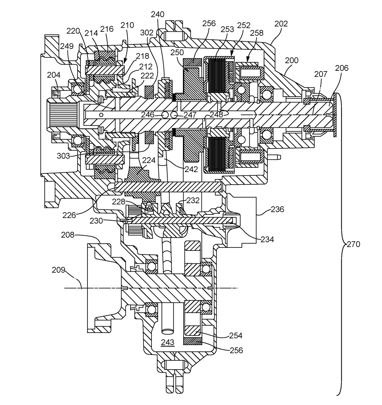
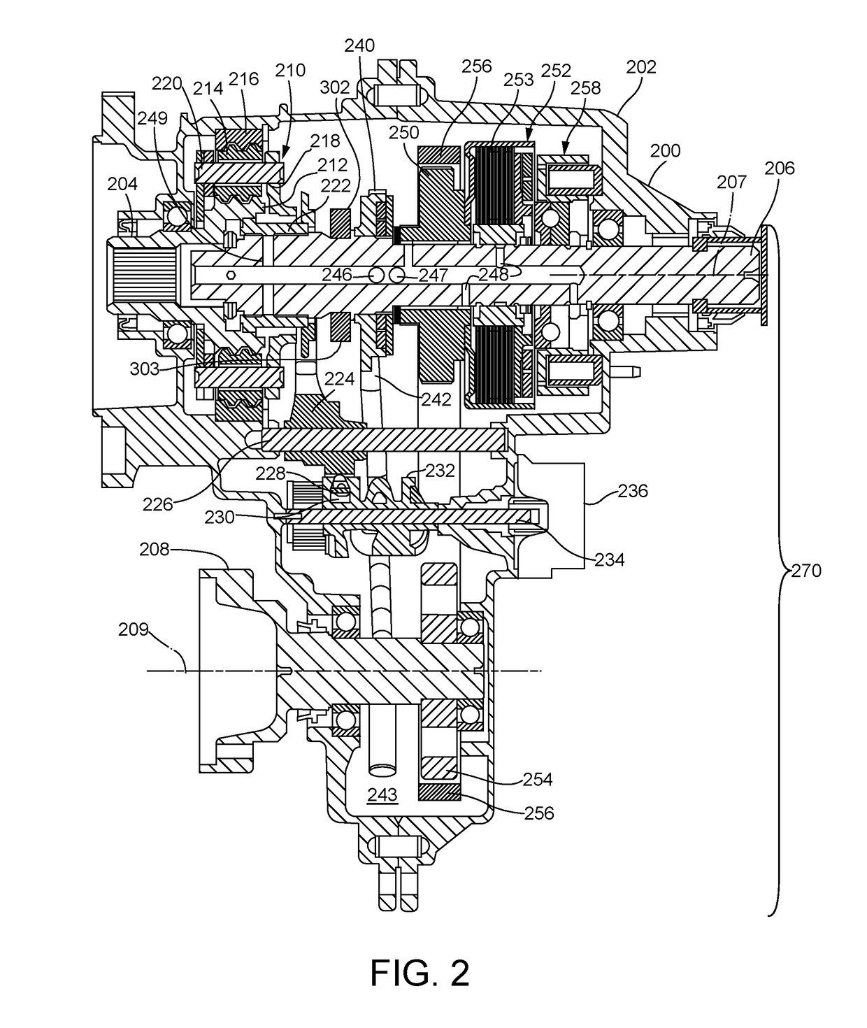
[0017]The disclosure herein is directed to a lubrication system for a transfer case comprising valve controls and a fluid guide insert located along the lubrication flow path between a sump, a pump, and various components of a power transfer assembly. The lubrication system can reduce the parasitic losses associated with driving pumping elements to pressurize lubricant. The lubrication system also can reduce spin losses associated with shear forces generated by an oil film between the friction and separator plates of a clutch when the clutch is not engaged.

[0018]Drivetrain and Transfer Case

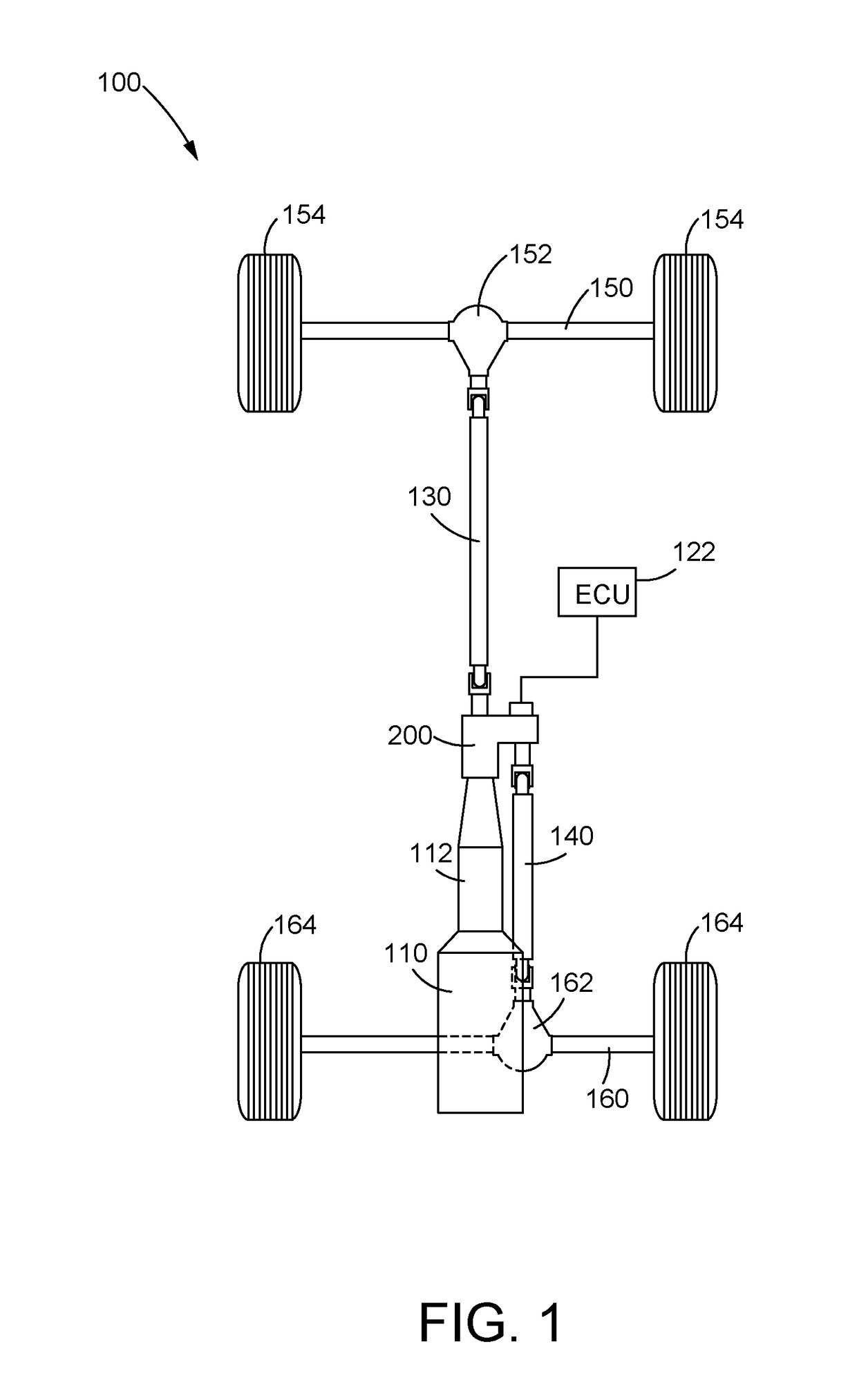
[0019]FIG. 1 is a plan view illustration showing a drivetrain 100 for a four-wheel drive vehicle. The drivetrain 100 includes an engine 110 that is coupled to a transmission 112. The engine 110 is the prime mover of the drivetrain 100 and can be, for example, an internal combustion engine, an electric motor / generator, or a combination of the two. Other types of prime movers can be utilized as the ...


PUM


Abstract

A lubrication system for a transfer case includes a pump in fluid communication with a lubricant source and a power transfer assembly, as well as one or more valves positioned along fluid flow paths between the lubricant source and the power transfer assembly. The valves may allow full fluid flow or may restrict fluid flow to various components of the transfer case as conditions warrant. A fluid guide insert may be used to help direct lubricant flow to the components.

Description

FIELD OF THE DISCLOSURE[0001]The present disclosure generally relates to a lubrication system for a transfer case. More specifically, the disclosure relates to a lubrication system including a pump in fluid communication with a lubricant source and a system for distributing the lubricant among various components on an as needed basis.BACKGROUND OF THE DISCLOSURE[0002]In the field of vehicle drivetrain components, a transfer case is an apparatus that distributes driving power to more than one driven axle of the vehicle. A typical transfer case receives driving power from the transmission of the vehicle and transfers that power to a primary output shaft that is driven constantly, for example, during operation of the vehicle in a two-wheel drive mode, and a secondary output shaft that is driven selectively using a clutch, for example, during operation of the vehicle in a four-wheel drive mode. In addition, two-speed transfer cases may provide gear reduction to allow operation in a high...

Claims


Application Information

Patent Timeline
IPC IPC(8): F16H57/04B60K17/344B60K23/08F16H37/06
CPCF16H57/0435B60K17/344B60Y2306/03F16H57/043F16H37/065B60K23/08B60K17/02B60K17/348B60K17/35F16H57/0473F16H57/0486F16H57/05
Inventor PALAZZOLO, MICHAEL ROBERTHASELTON, DAVID F.
Owner BORGWARNER INC
Why Eureka
Try Eureka