Signature velocity reduction device and method

a technology of velocity reduction and reduction device, which is applied in the direction of thin material processing, article separation, article delivery, etc., can solve the problems of product defects, deceleration solutions, and long time-consuming, and achieve the effect of reducing the time of deceleration and reducing the speed of the reduction devi

Active Publication Date: 2007-07-12
MANROLAND GOSS WEB SYST AMERICAS LLC
View PDF10 Cites 24 Cited by
  • Summary
  • Abstract
  • Description
  • Claims
  • Application Information

AI Technical Summary

Benefits of technology

[0004] In a first exemplary embodiment of the present invention, an apparatus for decelerating a signature comprises a movable belt arrangement, and a motor coupled to the movable belt arrangement for controllably moving the movable belt arrangement through a cyclical velocity profile. Pursuant to a feature of the present invention, the movable belt arrangement is moved through a signature engaging section with the cyclical velocity profile causing the motor to decelerate the movable belt arrangement from a first speed to a second speed while engaging a signature in the signature engaging section. The signature enters the signature engaging section at the first speed, and leaves the signature engaging section at the second speed, lower than the first speed. The cyclical velocity profile causes the movable belt arrangement to accelerate upon the signature leaving the signature engaging section, back to the first speed, prior to a next signature entering the signature engaging section.

Problems solved by technology

The constant stress of multiple decelerations of substantial numbers of signatures, as are encountered in commercial printing operations, causes durability problems with known deceleration solutions.
Moreover, in some known devices, the abrupt nature of the signature deceleration results in product defects.

Method used


Image

  • Signature velocity reduction device and method
  • Signature velocity reduction device and method
  • Signature velocity reduction device and method

Examples


Embodiment Construction

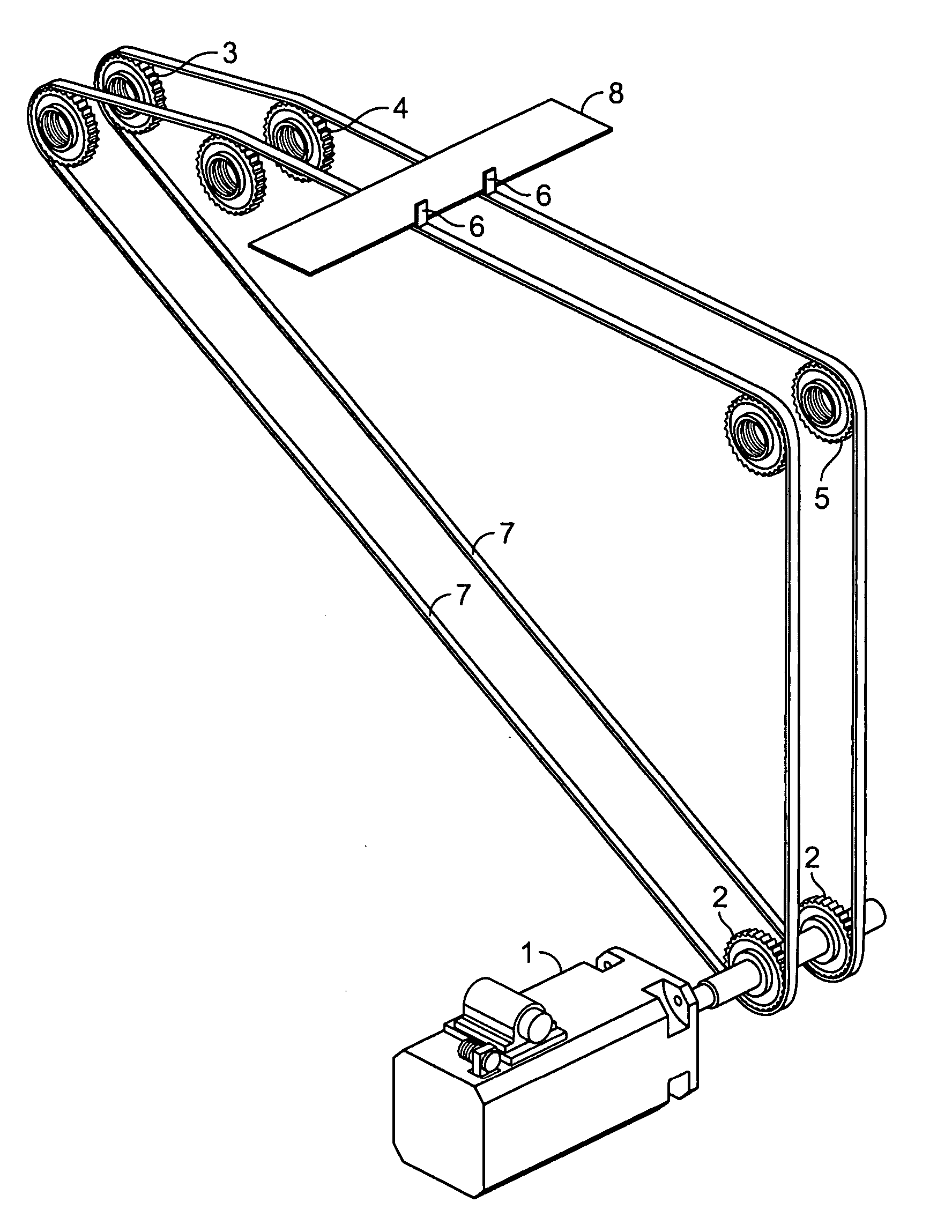
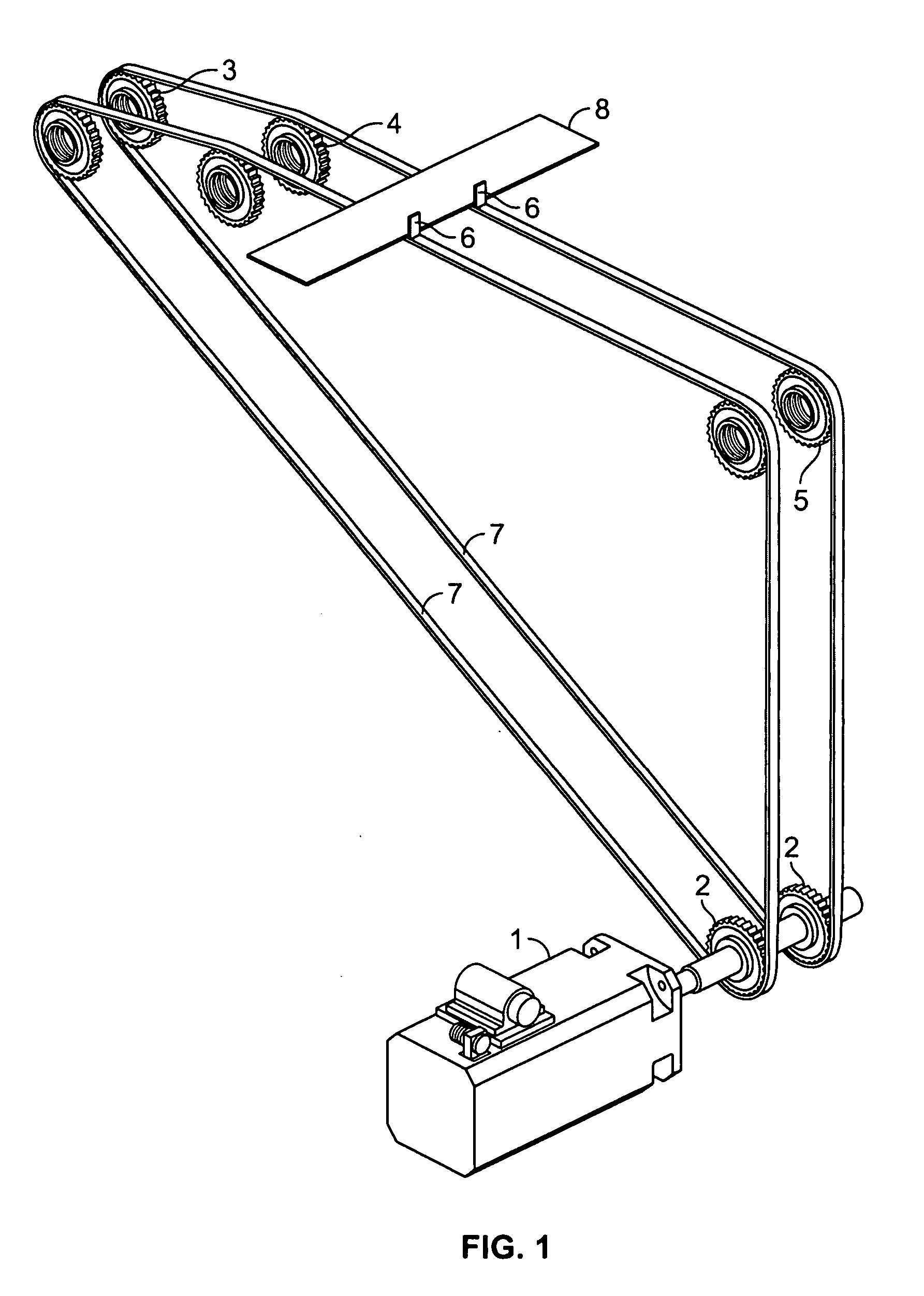
[0014] Referring now to the drawings, and initially to FIG. 1, there is shown a perspective view of a motor driven movable belt arrangement used as a signature deceleration mechanism, according to a feature of the present invention. A variable speed motor 1 is coupled to a drive sprocket assembly 2. A pair of belts 7 is arranged to extend around the drive sprocket assembly 2 for circulation through a path defined by the drive sprocket assembly 2 and idler sprockets 3, 4, 5. A pair of pins 6 is provided, each one of the pair 6 is mounted on a respective one of the belts 7 to register and align a signature 8 carried by the belts 7 from the idler sprockets 3 to the idler sprockets 5.

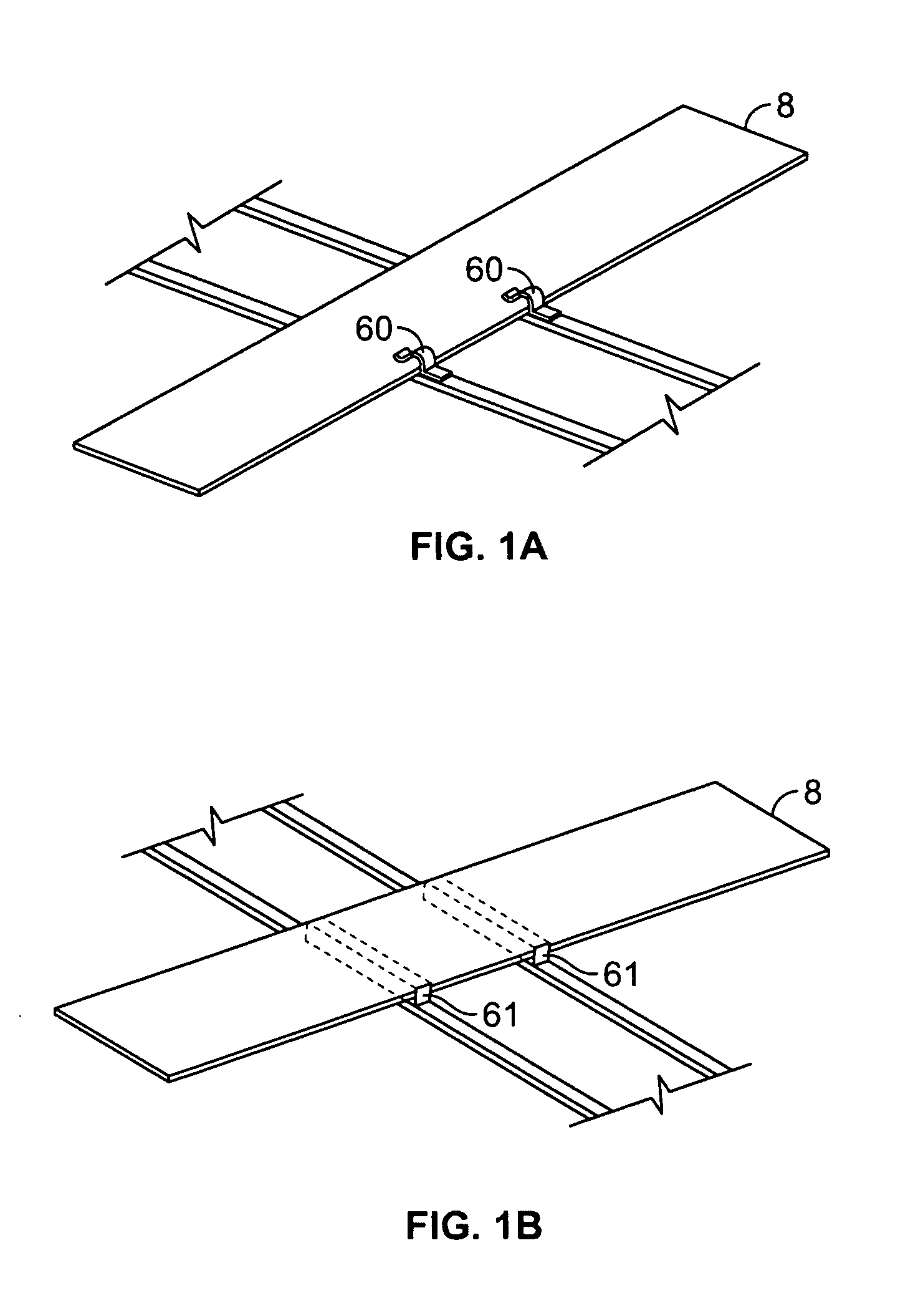
[0015]FIG. 1a shows an alternative embodiment for the pins of FIG. 1. In the embodiment of FIG. 1a, the structure arranged to register and align the signature 8 comprises a pair of grippers 60.

[0016]FIG. 1b shows a further alternative embodiment for the pins of FIG. 1. In the embodiment of FIG. 1b, the st...


PUM

PropertyMeasurementUnit
velocityaaaaaaaaaa
speedaaaaaaaaaa
cyclical velocityaaaaaaaaaa

Abstract

In a first exemplary embodiment of the present invention, an apparatus for decelerating a signature comprises a movable belt arrangement, and a motor coupled to the movable belt arrangement for controllably moving the movable belt arrangement through a cyclical velocity profile. Pursuant to a feature of the present invention, the movable belt arrangement is moved through a signature engaging section with the cyclical velocity profile causing the motor to decelerate the movable belt arrangement from a first speed to a second speed while engaging a signature in the signature engaging section. The signature enters the signature engaging section at the first speed, and leaves the signature engaging section at the second speed, lower than the first speed. The cyclical velocity profile causes the movable belt arrangement to accelerate upon the signature leaving the signature engaging section, back to the first speed, prior to a next signature entering the signature engaging section.

Description

BACKGROUND OF THE INVENTION [0001] In a printing operation, signatures are moved through a printing press at a maximum press speed that is considerably faster than can be accommodated in downstream equipment such as folders. Typically, signature speed is reduced by approximately 50% before input to a folder. [0002] In known printing press equipment, a deceleration mechanism is utilized to decelerate signatures as they exit a printing press, and prior to input to a folder. The deceleration mechanism implements mechanical structures that engage and decelerate the individual signatures. The constant stress of multiple decelerations of substantial numbers of signatures, as are encountered in commercial printing operations, causes durability problems with known deceleration solutions. Moreover, in some known devices, the abrupt nature of the signature deceleration results in product defects. SUMMARY OF THE INVENTION [0003] The present invention provides a new and improved apparatus and m...

Claims


Application Information

Patent Timeline
Patent Type & Authority Applications(United States)
IPC IPC(8): B65H5/34
CPCB65H29/16B65H29/68B65H2513/108B65H2404/232B65H2404/264B65H2301/4473B65H2513/10
Inventor COTE, KEVIN LAURENSCHROEDER, LOTHAR JOHNST.OURS, JOSEPH ADRIAN
Owner MANROLAND GOSS WEB SYST AMERICAS LLC
Why Eureka
Try Eureka