Digital recorder
- Summary
- Abstract
- Description
- Claims
- Application Information
AI Technical Summary
Benefits of technology
Problems solved by technology
Method used
Image

Examples
Embodiment Construction
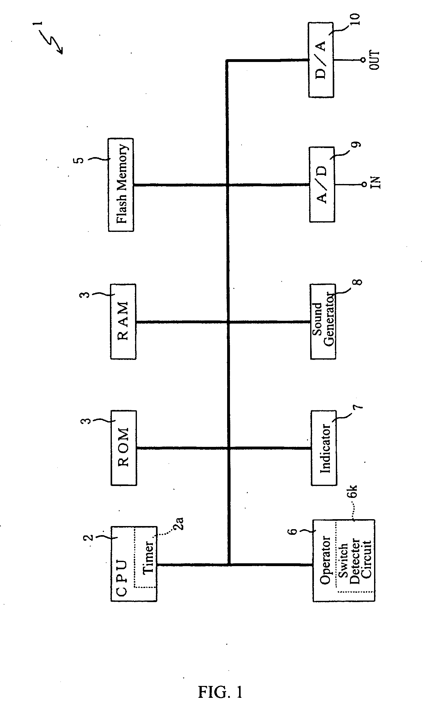
[0020]FIG. 1 is a block diagram that illustrates an electrical configuration of a recorder 1 according to an embodiment of the invention. The recorder 1 is composed of a central processing unit (CPU) 2, a read-only memory (ROM) 3, a random access memory (RAM) 4, a storage device such as a flash memory 5, an operator 6, an indicator 7, a sound generator 8, an analog-to-digital (A / D) converter 9 and a digital-to-analog (D / A) converter 10. The various components may be connected together via a bus or other suitable connection scheme.
[0021] The CPU 2 is provided with a control program, which may run the performance equipment (not shown) in its entirety. As such, each control program and its processes run from the CPU 2 may refer to a fixed value data that is stored in the ROM 3. In the CPU 2, when automatic performance data is formulated from real-time performance, the automatic performance data is formulated in reference to the timing kept by an embedded timer 2a.
[0022] The RAM 4 is ...
PUM
 Abstract
Description
Claims
Application Information