Frame structure

a technology for electronic cabinets and frames, applied in the field of frame structures, can solve the problems of relatively complicated frame structures, which cannot be manufactured, and achieve the effect of improving the service life of the structur

Inactive Publication Date: 2007-08-02
KNUERR AG
View PDF25 Cites 23 Cited by
  • Summary
  • Abstract
  • Description
  • Claims
  • Application Information

AI Technical Summary

Benefits of technology

[0011] The object of the invention is to provide a frame structure for electronic cabinets, particularly those in network and telecommunications technology, as well as for cabinet rows, which in the case of an inexpensive manufacture and installation ensure unhindered laying of relatively large cable quantities and differing bendability, together with a vertical and horizontal cable routing without threading.
[0016] Preferably the connection of the vertical members to the upper and lower depth members takes place by welding and the thus formed unit is advantageous for the storage, transportation and installation of the frame structure.
[0022] The necessary stability of the inventive frame structure is achieved through multiply folded or bent vertical members and depth and transverse members constructed as C and / or U-beams.
[0029] It is advantageous that the depth members can also be manufactured from a sheet steel blank by multiple bends and punching out. The connection points integrated into the depth members can also be used for a detachable fixing of a rear wall and side walls, as well as a cover and a bottom plate.
[0032] The fixing plates of the transverse members are provided with fixing side plates to increase stability and the supporting function and they are bent at right angles and embrace or engage on end regions of the vertical legs and a horizontal marginal web of the transverse members in each case.
[0034] It falls within the scope of the present invention through a simple modification of the recess in the depth members, to arrange and connect the vertical members eccentrically for forming different front and rear frame recesses.

Problems solved by technology

The known frame structures, which are relatively complicated to manufacture, do not in all cases satisfy the demands for an unhindered cabling and vertical and horizontal cable routing with free access to the cabling areas, particularly in the case of cabinet rows with laterally adjacent cabinets.

Method used


Image

  • Frame structure
  • Frame structure
  • Frame structure

Examples


Embodiment Construction

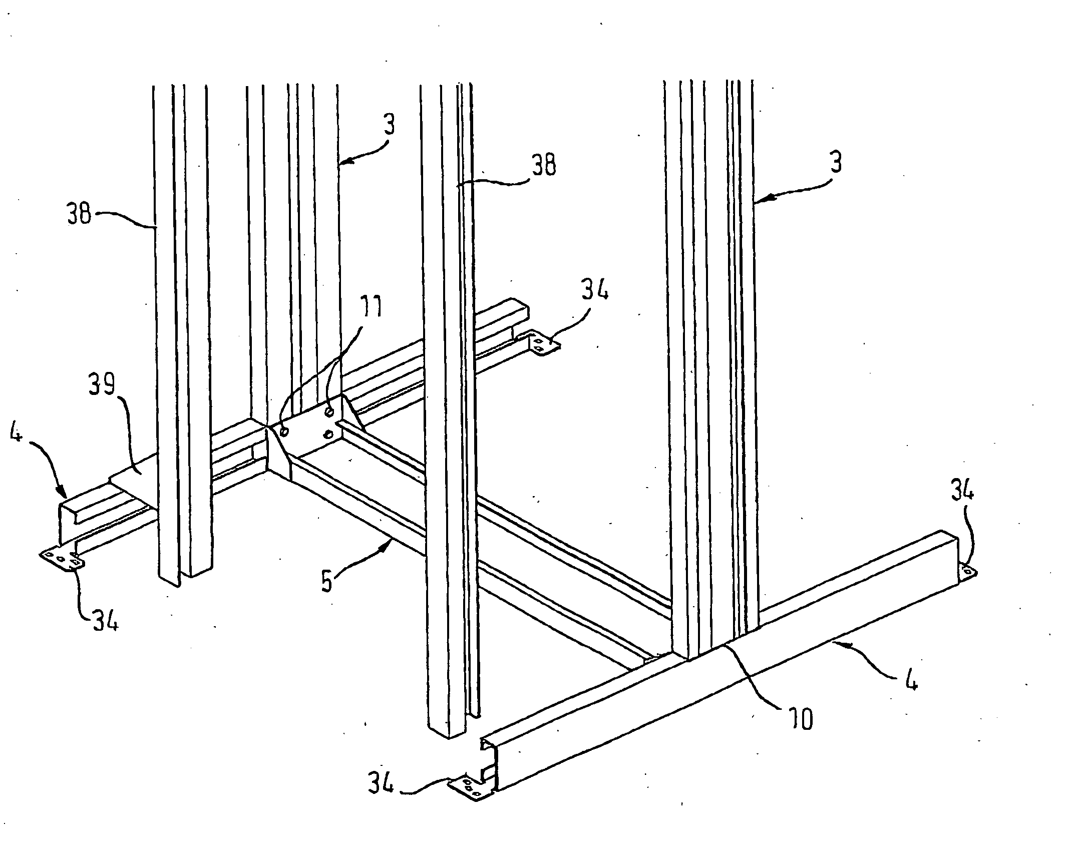
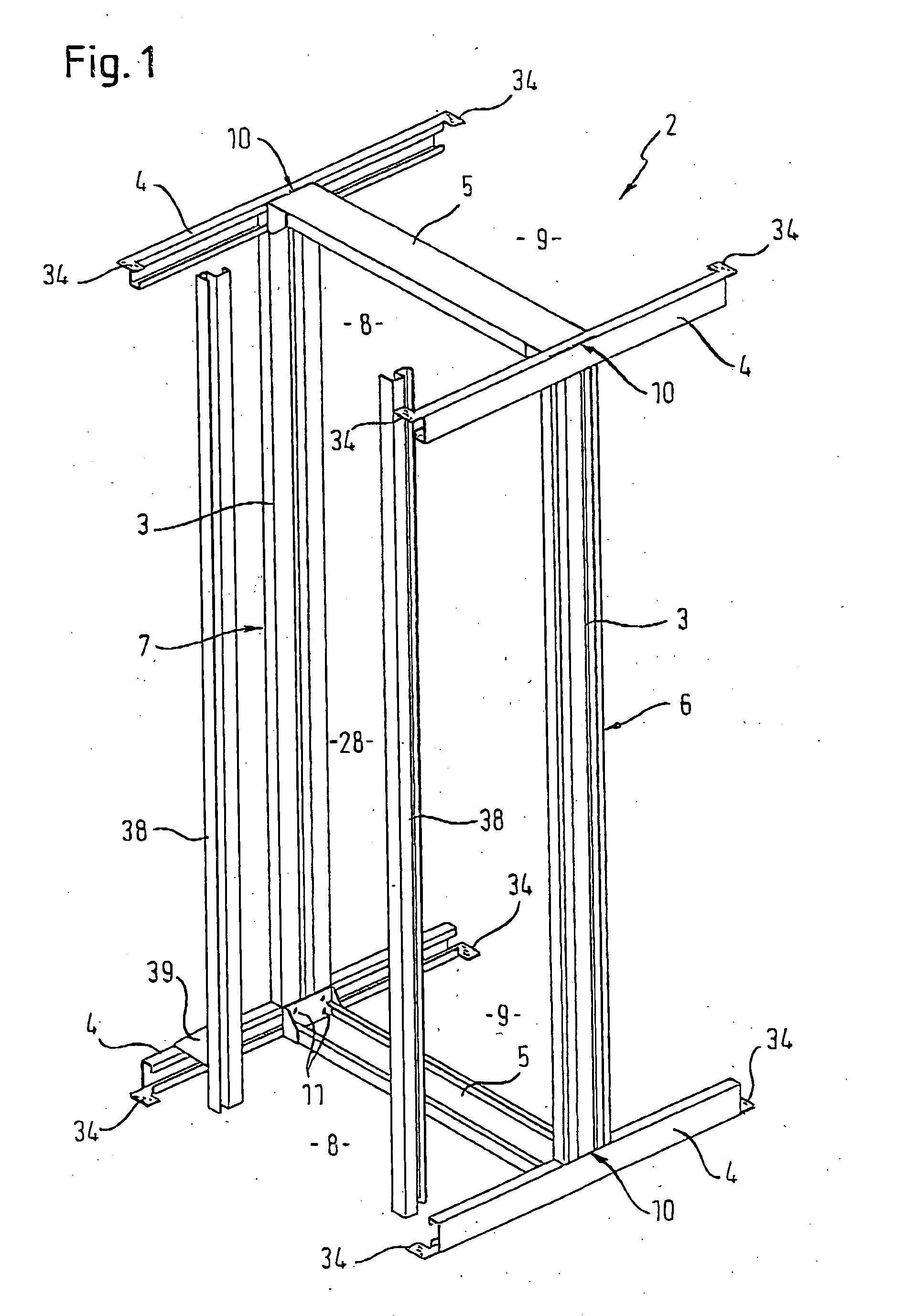
[0042]FIG. 1 shows a frame structure 2 ensuring high stability and unhindered cabling and cable routing in all directions and therefore an advantageous use for network cabinets and cabinet rows with high cabling densities.

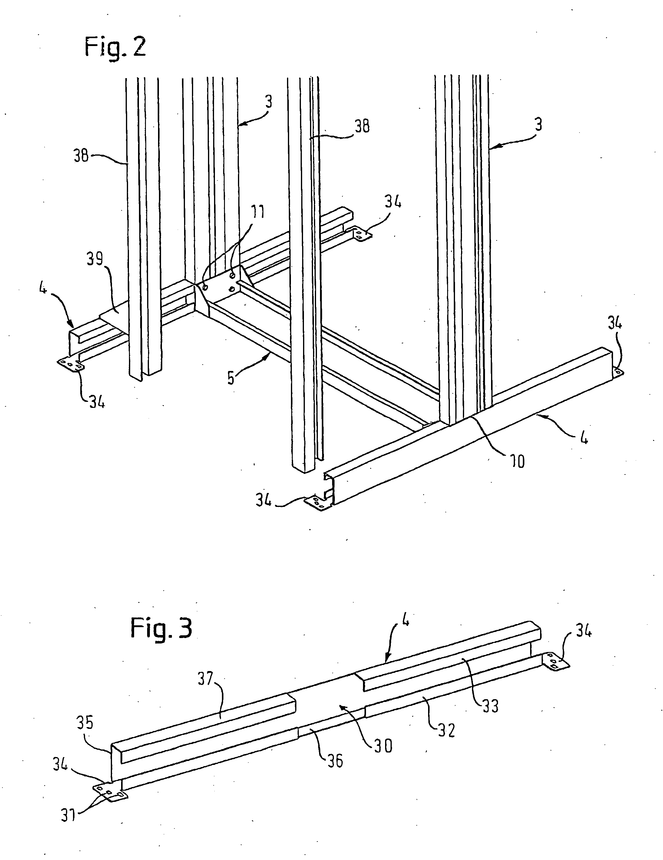
[0043] The frame structure 2 comprises two vertical members 3, four depth members 4 and two transverse members 5, which are so positioned and interconnected that a frontal frame recess 8 and a rear frame recess 9 are formed. FIG. 1 and the larger scale partial representation of FIG. 2 make it clear that cable routing without disadvantageous threading is possible, because both the generally conventional front and rear vertical members and also the front and rear upper and lower transverse members are omitted.

[0044] High stability and simultaneously advantageous accessibility and cabling are achieved through the connection of in each case one vertical member 3 to a depth member 4 fixed to the upper and lower end so as to form a double-T frame. The connection of the...


PUM


Abstract

The invention relates to a rack or frame structure for electronic cabinets, specifically for network cabinets and cabinet rows with high cabling densities. To ensure in the case of high stability unhindered access to a reception area and cable routing in each direction, two vertical members and four depth members are so connected that a right and left-hand double-T frame is formed. The vertical members are in particular positioned as central members. The preferably releasable connection of the right and left-hand double-T frame takes place with the aid of a lower and upper transverse member in the vicinity of the vertical members, accompanied by the formation of a front and a rear frame recess.

Description

BACKGROUND AND SUMMARY OF THE INVENTION [0001] 1. Field of the Invention [0002] The invention relates to a rack or frame structure for electronic cabinets with a right and a left-hand vertical member, two upper and lower depth members and with transverse members. [0003] The invention is particularly suitable for instrument and equipment cabinets used for setting up local networks and for receiving electrical, electronic and optoelectronic equipment, parts and components and which are intended to receive relatively large cable quantities, as well as cables with different diameters. [0004] 2. Discussion of the Background [0005] Known frame structures for equipment cabinets have an upper and a lower, horizontal frame of in each case two depth and transverse members. The frames are interconnected by four vertical members in the corner regions and as a result a reception area for equipment, components and cables is formed. To the frame structure can be fitted covering parts, e.g. a front...

Claims


Application Information

Patent Timeline
Patent Type & Authority Applications(United States)
IPC IPC(8): A47F7/00
CPCH04Q1/064H04Q1/062H04Q1/025
Inventor BUMEDER, GERHARDKNAB, JOSEFSCHNEIDERBAUER, SIEGFRIEDPRINZ, ALEXANDERSPATENEDER, WERNER
Owner KNUERR AG
Why Eureka
Try Eureka