Stent graft including expandable cuff

a cuff and stent technology, applied in the field of treating a deformity, can solve the problems of difficult treatment of aneurysms, requiring a significant amount of time in an intensive care unit, and causing death

Inactive Publication Date: 2007-08-02
VARDI GIL
View PDF40 Cites 56 Cited by
  • Summary
  • Abstract
  • Description
  • Claims
  • Application Information

AI Technical Summary

Problems solved by technology

Left untreated, an aneurysm may rupture causing fatal hemorrhaging.
The patient is placed under general anesthesia and requires a significant amount of time in an intensive care unit following the procedure for post-operative recovery.
A problem with the existing stent graft configurations is the difficulty of treating aneurysms located near a bifurcation in the vasculature.
Another problem is the insertion of large profile devices designed to fit within the aorta, which requires a surgical incision.

Method used


Image

  • Stent graft including expandable cuff
  • Stent graft including expandable cuff
  • Stent graft including expandable cuff

Examples


Embodiment Construction

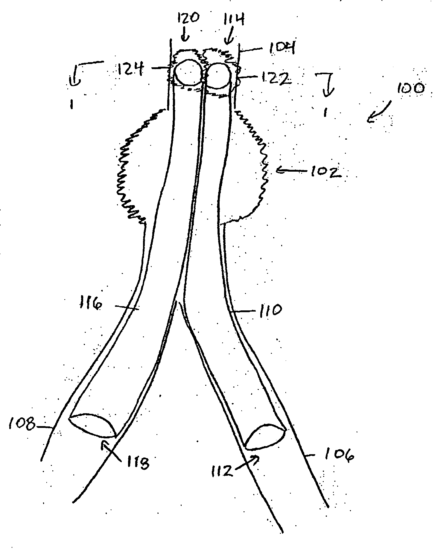
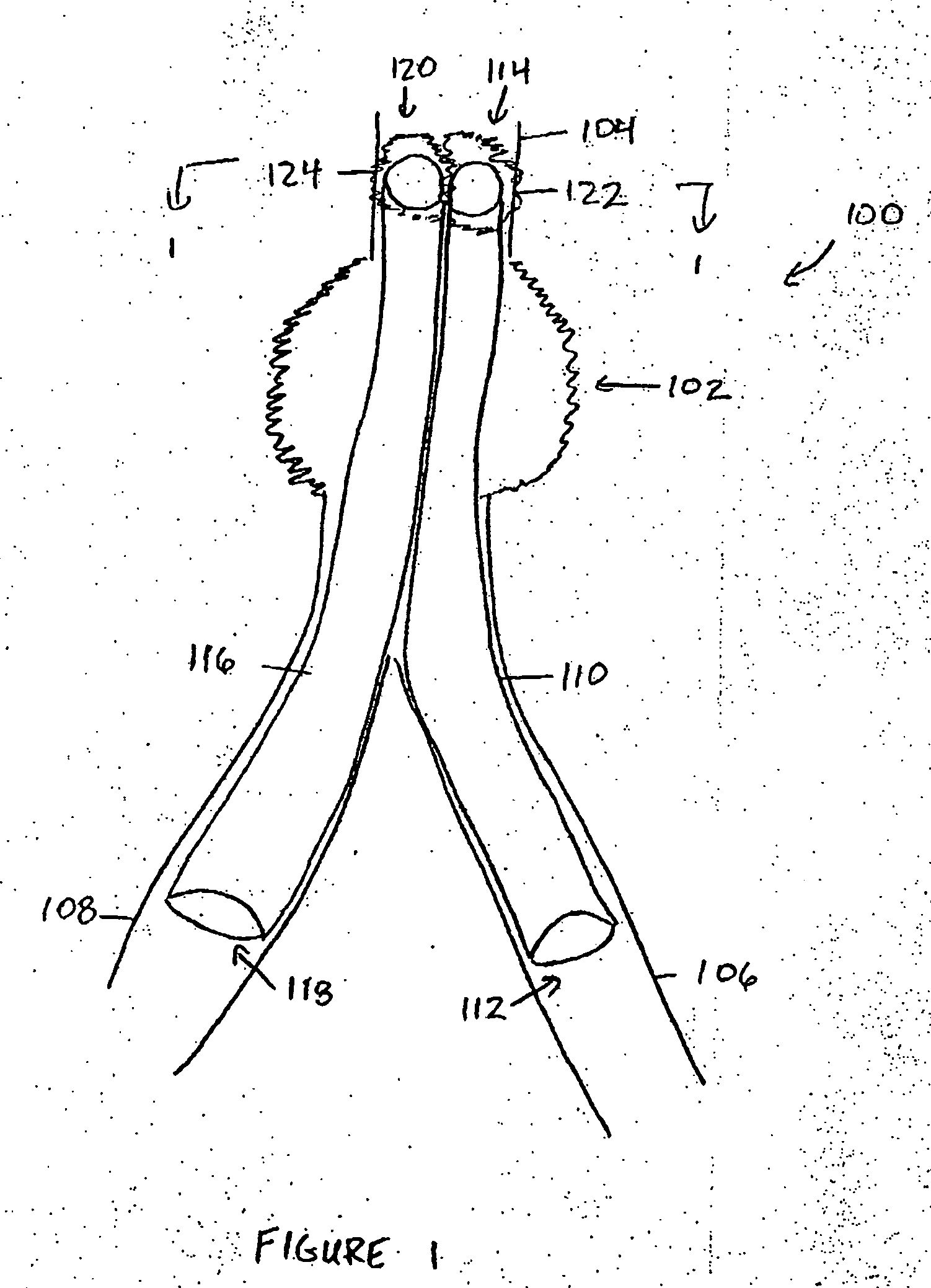
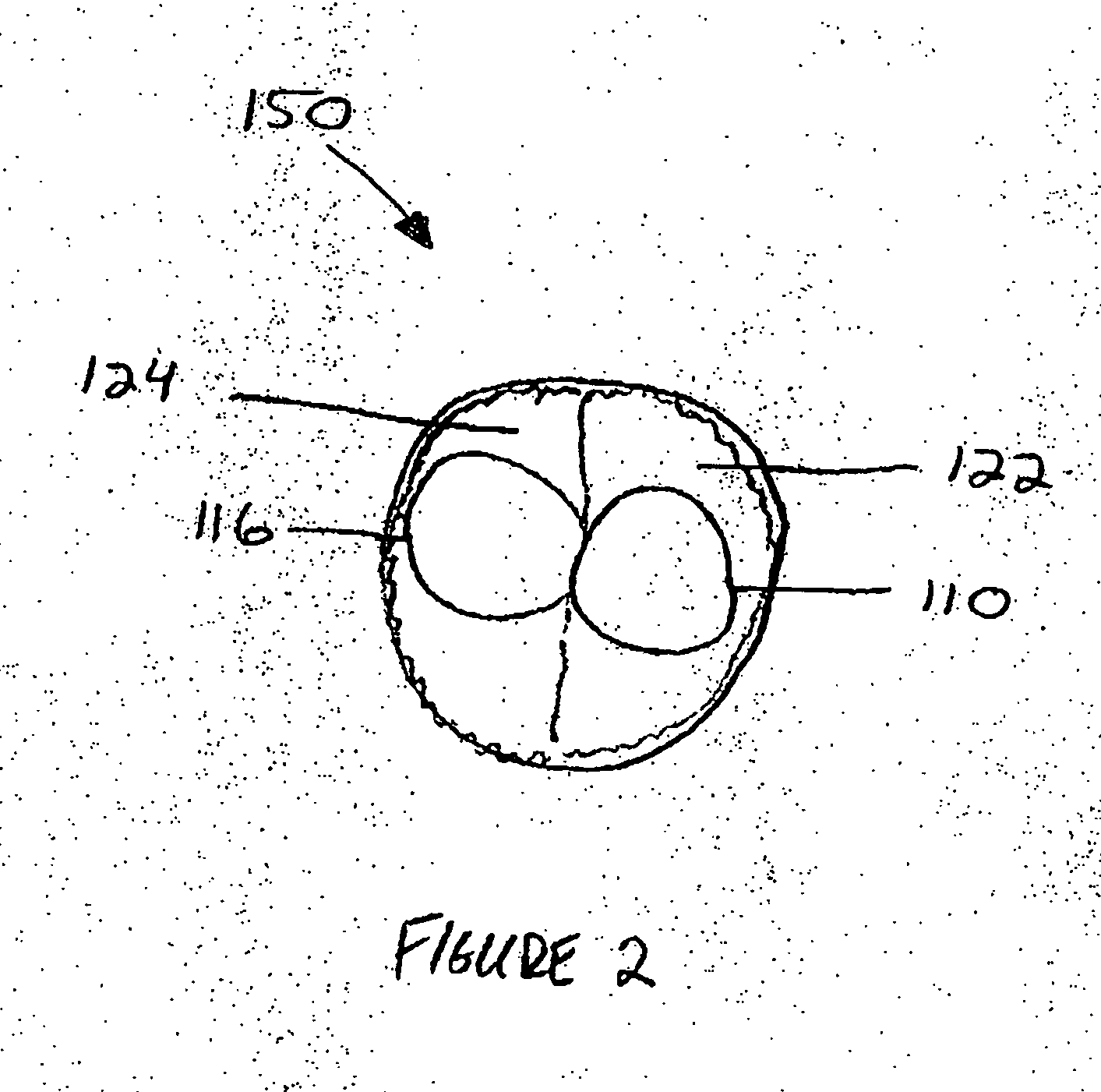
[0022] Exemplary embodiments of stent grafts are described below. In one embodiment, a stent graft assembly includes at least one stent graft having an expandable cuff at one end. A second stent graft may be employed at the same location to accommodate a branched artery or a larger size than can be percutaneously inserted. In one embodiment, the cuff is inflatable, while in an alternative embodiment, the cuff includes a sponge material that expands upon exposure to moisture. In a further embodiment, the stent graft includes a first cuff located at the distal end and a second cuff located at the proximal end. In a further embodiment, each stent graft has a flattened side and when the stent grafts are placed within a vessel.

[0023] The methods and apparatus for a stent graft described herein are illustrated with reference to the figures wherein similar numbers indicate the same elements in all figures. Such figures are intended to be illustrative rather than limiting and are included ...


PUM


Abstract

A graft for facilitating treatment of a deformity in a blood vessel wall includes a tubular body defining a first end and an opposing second end. At least a portion of the tubular body includes a hydrogel material configured to expand upon exposure to moisture.

Description

CROSS REFERENCE TO RELATED APPLICATIONS [0001] This application is a continuation-in-part application of application Ser. No. 10 / 958,119 filed on Oct. 4, 2004, which is hereby incorporated by reference in its entirety.BACKGROUND OF THE INVENTION [0002] This invention relates generally to treatment of a deformity in a blood vessel and, more particularly, to methods and apparatus for treating a deformity, such as an aneurysm, in a blood vessel wall. [0003] Stent grafts may be used to treat aneurysms in a patient's vascular system. An aneurysm is a degeneration of a blood vessel wall whereby the wall may weaken and balloon outwardly. Left untreated, an aneurysm may rupture causing fatal hemorrhaging. Conventional stent grafts typically include a stent forming an elongated tubular wire frame that provides structural support for the vessel wall and a tubular graft positioned about the wire frame to facilitate blood flow through the blood vessel while preventing blood flow into the aneury...

Claims


Application Information

Patent Timeline
Patent Type & Authority Applications(United States)
IPC IPC(8): A61F2/06
CPCA61F2/07A61F2002/067A61F2210/0061A61F2250/0003A61F2230/0034A61L27/507A61L31/14A61F2002/072A61F2002/075A61L27/50
Inventor VARDI, GIL
Owner VARDI GIL
Why Eureka
Try Eureka