
Method and apparatus for estimating object part location in digital image data using feature value analysis

a technology of feature value analysis and object part location, applied in the field of digital image processing technique, can solve the problems of restricting the detection process, complicated face identification task, and inability to find reference images

Active Publication Date: 2007-08-09
FUJIFILM CORP
View PDF8 Cites 7 Cited by
  • Summary
  • Abstract
  • Description
  • Claims
  • Application Information

AI Technical Summary

Problems solved by technology

The task of face identification is complicated by non-face areas and objects present in images, as well as by variability in pose, lighting, expression, etc., of people's faces in images.
This method, however, is dependent on the existence of a reference image of an object, and in many cases such a reference image is not available.
This method, however, uses predetermined characteristics of target objects, which might restrict the detection process and present challenges when presented with objects of variable characteristics, or with objects that do not feature the predetermined characteristics.

Method used


Image

  • Method and apparatus for estimating object part location in digital image data using feature value analysis
  • Method and apparatus for estimating object part location in digital image data using feature value analysis
  • Method and apparatus for estimating object part location in digital image data using feature value analysis

Examples


second embodiment

[0038]FIG. 5 is a block diagram of a training system 310 included in an image processing unit 128A for object part location estimation using feature value analysis according to the present invention illustrated in FIG. 4. As shown in FIG. 5, training system 310 includes: a training images processing unit 320; a quantizer unit 403; a classifier unit 405; a features extractor unit 409; and a feature space analysis training unit 411. Quantizer unit 403, classifier unit 405, features extractor unit 409 and feature space analysis training unit 411 are included in part location training unit 330. The units included in training system 310 implement algorithms to perform training for position estimation of object parts included in a type of objects. Training images processing unit 320 produces and processes training sub-images. The training sub-images contain object parts typical to the objects for which training system 310 trains. As an example, if training system 310 trains for position e...

third embodiment

[0053]FIG. 14 illustrates aspects of the operation for face registration performed by an image registration unit 901 included in a system 129 for face recognition according to the present invention illustrated in FIG. 13. An image I950 with localized object parts output by an image processing unit 128 is compared with a template image T960. For this purpose, the positions of object parts P951, P952, P953 and P954 (eyes and mouth corners) are compared with the positions of the eyes and mouth corners P961, P962, P963 and P964 of the template image T960. A transformation is applied including rotation, translation and scaling, to obtain transformed image I970 which has the same orientation, size, and rotational position as the template image T960. Well-registered faces such as transformed image I970 give better face recognition results.

[0054] The embodiments described above can be used for estimating object part locations using feature value analysis in various technologies. Examples of...


PUM


Abstract

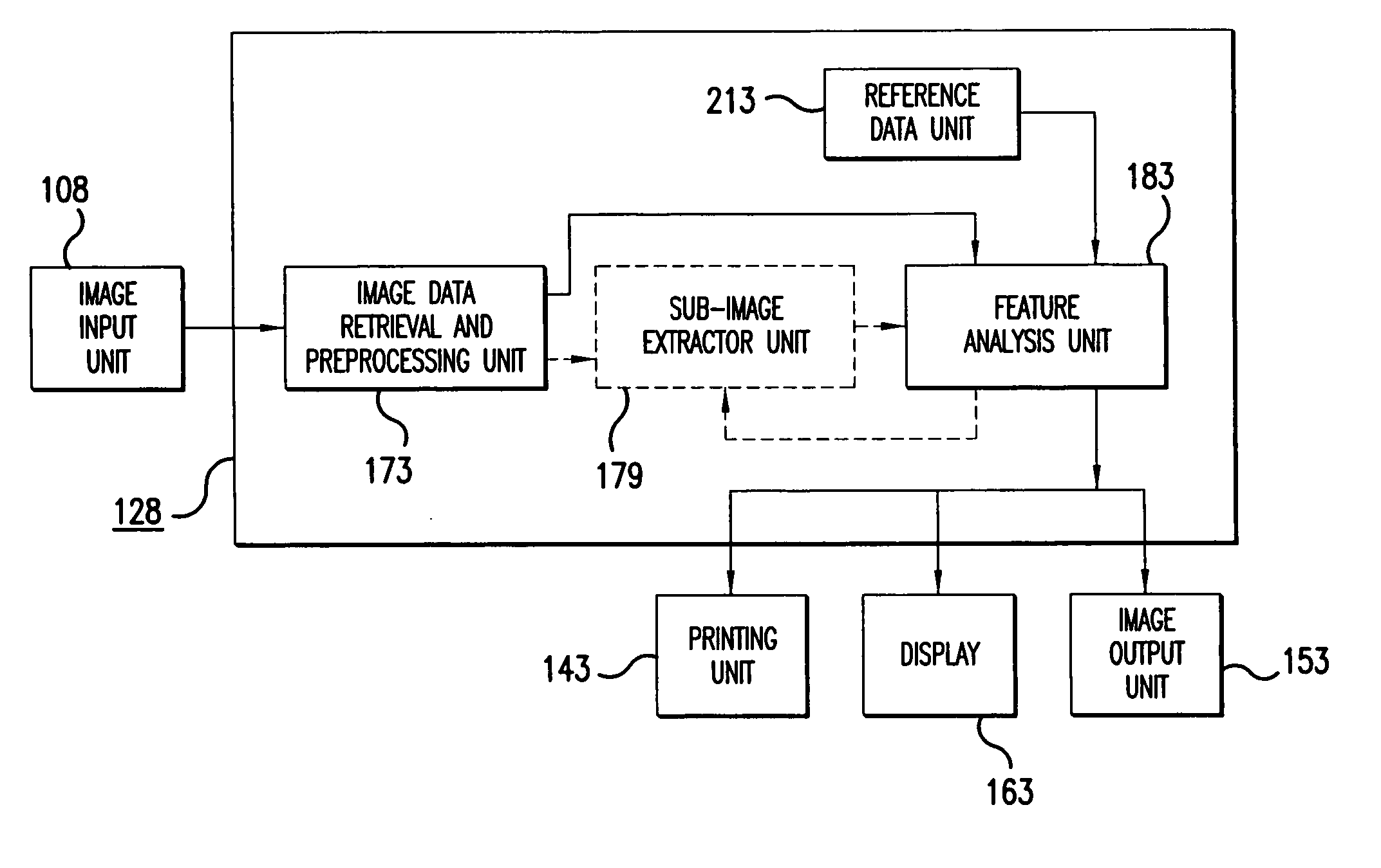
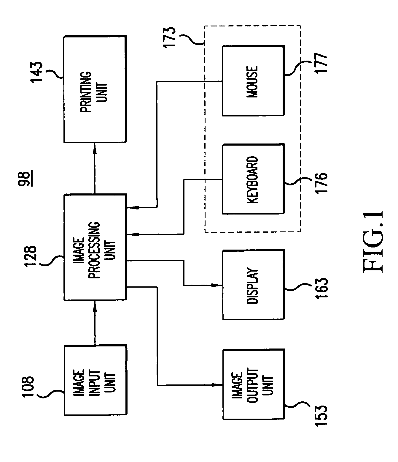
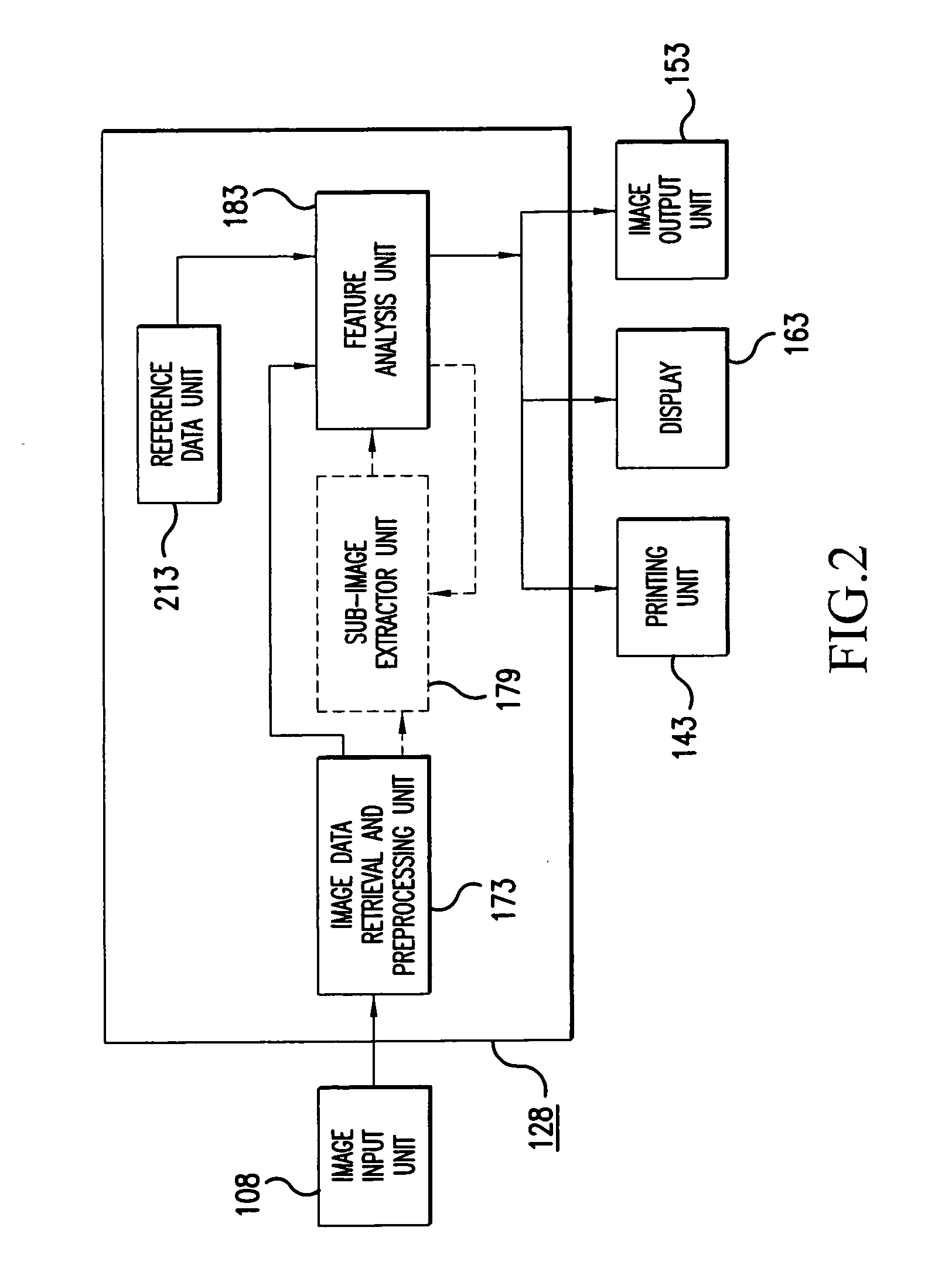
A method and an apparatus estimate an object part location in a digital image using feature value analysis. The method according to one embodiment accesses digital image data representing a region including an object part of a digital image; accesses reference data including class data of classes relating to predetermined positions of the object part in predetermined regions, and features that discriminate among the classes; calculates feature values for the features in the region using pixel values within the region; and determines a location estimate of the object part using the feature values and the reference data.

Description

CROSS-REFERENCE TO RELATED APPLICATION [0001] This non-provisional application is related to co-pending non-provisional application titled “Method and Apparatus for Localizing an Object Part in Digital Image Data” filed concurrently herewith, the entire contents of which are hereby incorporated by reference.BACKGROUND OF THE INVENTION [0002] 1. Field of the Invention [0003] The present invention relates to a digital image processing technique, and more particularly to a method and apparatus for locating objects in a digital image. [0004] 2. Description of the Related Art [0005] Face recognition plays an important role in digital image processing techniques concerned with the study and processing of human faces. Face recognition systems can be included in security systems used in identification of people's identities; can help organize media such as photographs that include faces; etc. [0006] When presented with images including people and objects, a known face recognition system ide...

Claims


Application Information

Patent Timeline
Patent Type & Authority Applications(United States)
IPC IPC(8): G06K9/36G06K9/46G06K9/62
CPCG06K9/00248G06V40/165
Inventor IOFFE, SERGEY
Owner FUJIFILM CORP
Learn More