Deep c parts and method of molding

a cross-sectional, deep technology, applied in the direction of transportation and packaging, coatings, other domestic articles, etc., can solve the problems of tearing, rippling or other displacement of the film, difficult to remove the part from the mold cavity, and difficult to mold such substantially “c” cross-sectioned plastic parts, etc., to achieve the effect of reducing the pinching, rippling or tearing of the edg

Inactive Publication Date: 2007-08-16
GREEN TOKAI
View PDF12 Cites 5 Cited by
  • Summary
  • Abstract
  • Description
  • Claims
  • Application Information

AI Technical Summary

Benefits of technology

[0012] Additionally, the female mold member of the mold is withdrawn from the stationery male mold member at an angle of from about 1-20°, similar to the angle of the inclined bottom wall of the nadir section. This helps to minimize pinching, rippling, or tearing of the edge of a paint film that is disposed in the nadir cavity during ejection or removal of the part from the mold.

Problems solved by technology

Molding of such deep drawn substantially “C” cross sectioned plastic parts, in particular, is difficult however.
If the opposed edges of the “C” converge too greatly toward each other, it is difficult to remove the part from the mold cavity.
Moreover, removing of the part from the mold often results in tearing, rippling or other displacement of the film that is disposed along the show surface of the part.
Undesirable distortions or damage of the opposed edges of the part may also occur during removal of the part from the mold cavity.
As a result, the color, gloss or other finish qualities of the part may be impaired.

Method used


Image

  • Deep c parts and method of molding
  • Deep c parts and method of molding
  • Deep c parts and method of molding

Examples


Embodiment Construction

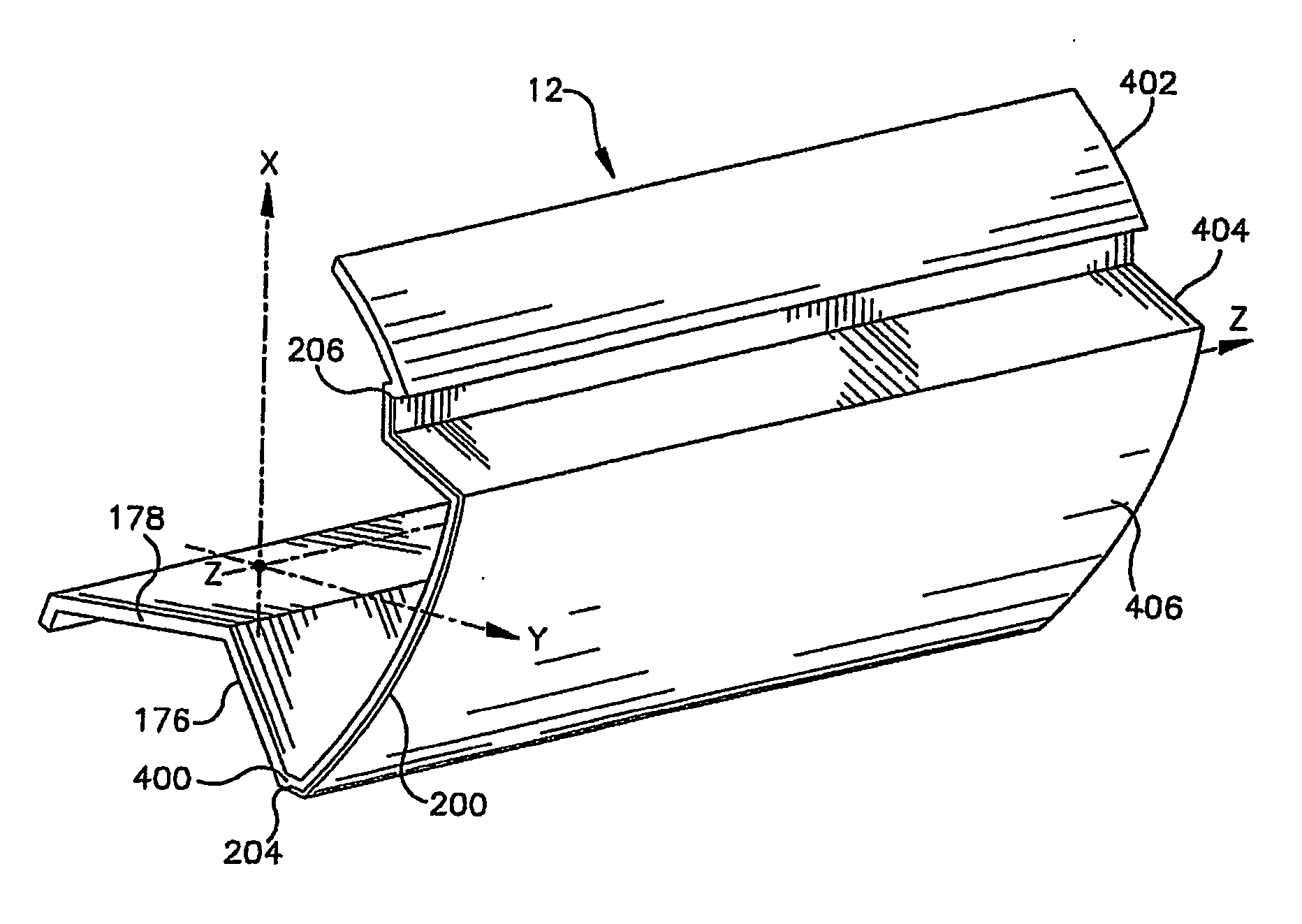
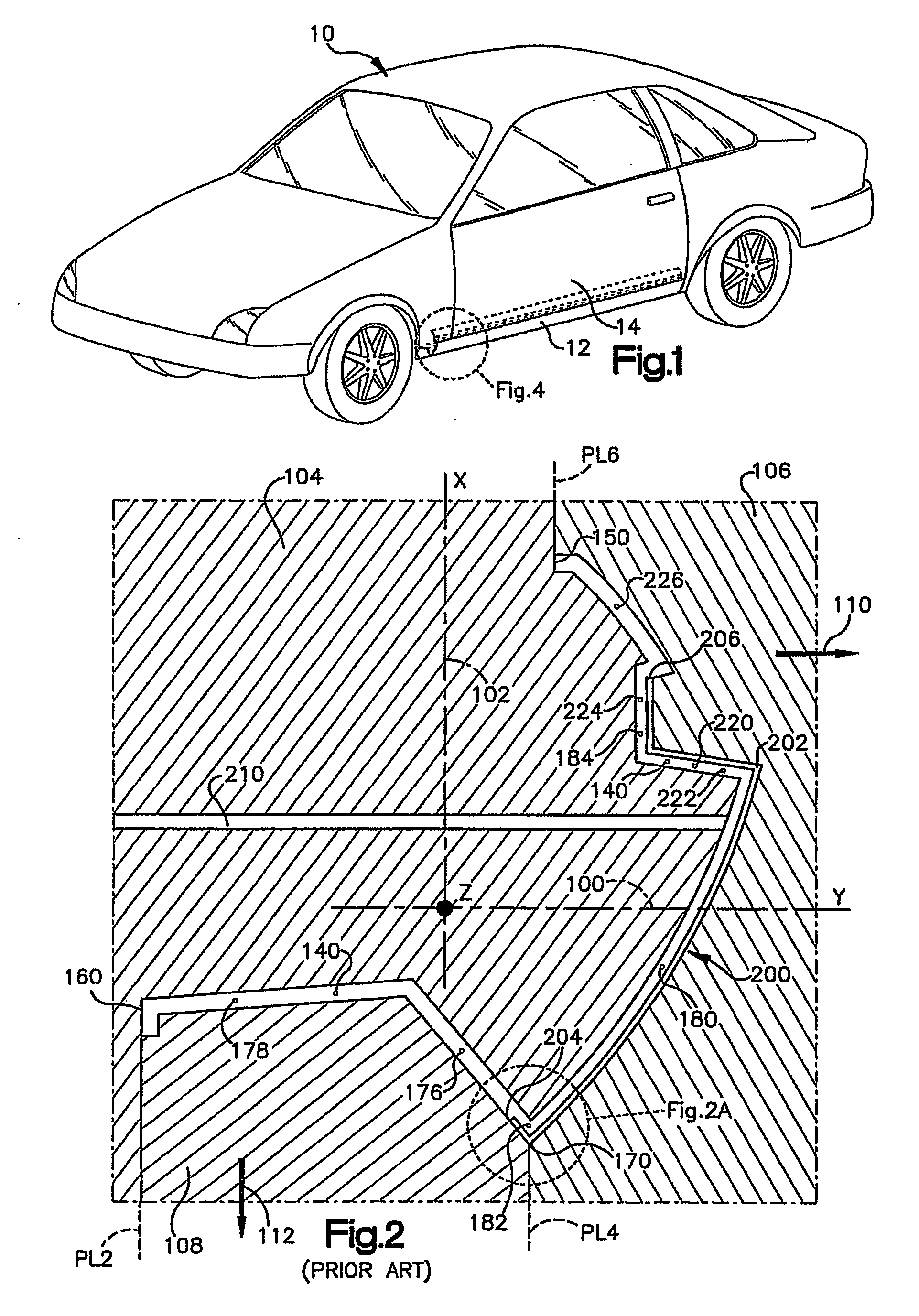
[0021] Turning first to FIG. 1, there is shown an automobile 10 of the type in which elongated part 12 in accordance with the invention may be used. As shown, part 12 is a side sill garnish or as sometimes referred to, a rocker panel. An upper portion of the part 12 is hidden by the contiguous body member or other trim member 14.

[0022] As shown in FIG. 4, the part 12 comprises an elongated member composed of a major showside surface area 406 that is located intermediate nadir wall 400 and apex wall components 402, 404. Paint film 200 covers the entirety of the major showside surface 406. A bottom edge or extremity 204 of the paint film is located along nadir wall 400 behind the nadir of the part. Legs 176 and 178 extend rearwardly spaced from the show surface of the part. A top edge of the paint film 206 is positioned on the outer surface of the part along apex wall component 404.

[0023] As shown, the part includes a Z direction, namely the longitudinal axis of the part, along with...


PUM

PropertyMeasurementUnit
angleaaaaaaaaaa
angleaaaaaaaaaa
angleaaaaaaaaaa

Abstract

An elongated, substantially “C” cross sectioned part and method of making same are provided wherein the part may be injection. molded and covered with portions. The method includes, the provision of a mold cavity having an inclined nadir wall boundary (182) and moving (358) the female mold mold part (104) an angle of about 1-20° relative to the widthwise or Y direction. The part includes a plastic substrate and an optional paint film having one edge (204) wall (182) behind the show surface (200) of the part.

Description

CROSS-REFERENCE TO RELATED APPLICATION [0001] This application claims the priority benefit of U.S. Provisional Patent Application Ser. No. 60 / 505,459 filed Sep. 24, 2003.BACKGROUND OF THE INVENTION [0002] 1. Field of Invention [0003] This invention relates to deep “C” cross-section molded parts and methods of making such parts. [0004] 2. Description of Related Art [0005] Automotive trim parts and protective molding are often prepared via injection molding techniques with the manufacture of elongated moldings being greatly aided by gas assisted injection molding techniques. For some applications, it is desirable to form deep drawn molded parts wherein the transverse cross section of the elongated part approximates the letter “C”. [0006] For example, it is desirable to provide deep drawn side sill and rocker panel moldings for automobiles, for example, wherein the exterior show surface of the part (i.e., the outer part surface between the opposed generally horizontal ends of the “C”) ...

Claims


Application Information

Patent Timeline
Patent Type & Authority Applications(United States)
IPC IPC(8): B29C45/00B29C45/14B32B1/00B29C33/00B29C33/44B60R13/02B60R13/04
CPCB29C33/005B29C33/44B29C45/14B29C45/14778B29C45/44B29C2045/14901B29C2045/1495B29K2995/002B29L2031/30B29L2031/302Y10T428/24198Y10T428/24628
Inventor YAMAMOTO, HIROAKI
Owner GREEN TOKAI
Why Eureka
Try Eureka