Tire positioning sensor

Active Publication Date: 2005-09-01
MICRO POISE MEASUREMENT SYST
View PDF5 Cites 26 Cited by
  • Summary
  • Abstract
  • Description
  • Claims
  • Application Information

AI Technical Summary

Benefits of technology

[0011] When a tire to be chucked is placed between the rim halves, the chuck is extended toward the spindle to chuck the tire at a normally high rate of speed. When the chuck assembly is close enough to the tire, so that the tire is within the range of the sensors, the sensors measure the distance to the respective area of the sidewall of the tire. The programmable controller calculates the apparent slope of the sidewall plane from the sensor measurements and known distances between the sensors. If the calculated slope is too great, it is an indication that the tire is tilted and is at risk to be mis-chucked. When it is determined that a tire is at risk to be mis-chucked, movement of the chuck is slowed and the proxi

Problems solved by technology

During operation of the machine, occasions occur where the tire is not placed in the proper location for engagement by the rim halves.
This mislocation can result in the tire being pinched by the rim halves or pinched between the male and female conical tapers, permanently damaging the tire.
If the spindle is rotated in this condition, the part of the tire extending further from the rim halves can impact with various precision measurement devices placed in close proximity of the tire resulting in possible damage to the devices and/or tire.
Damaged tires must be destr

Method used


Image

  • Tire positioning sensor
  • Tire positioning sensor
  • Tire positioning sensor

Examples


Embodiment Construction

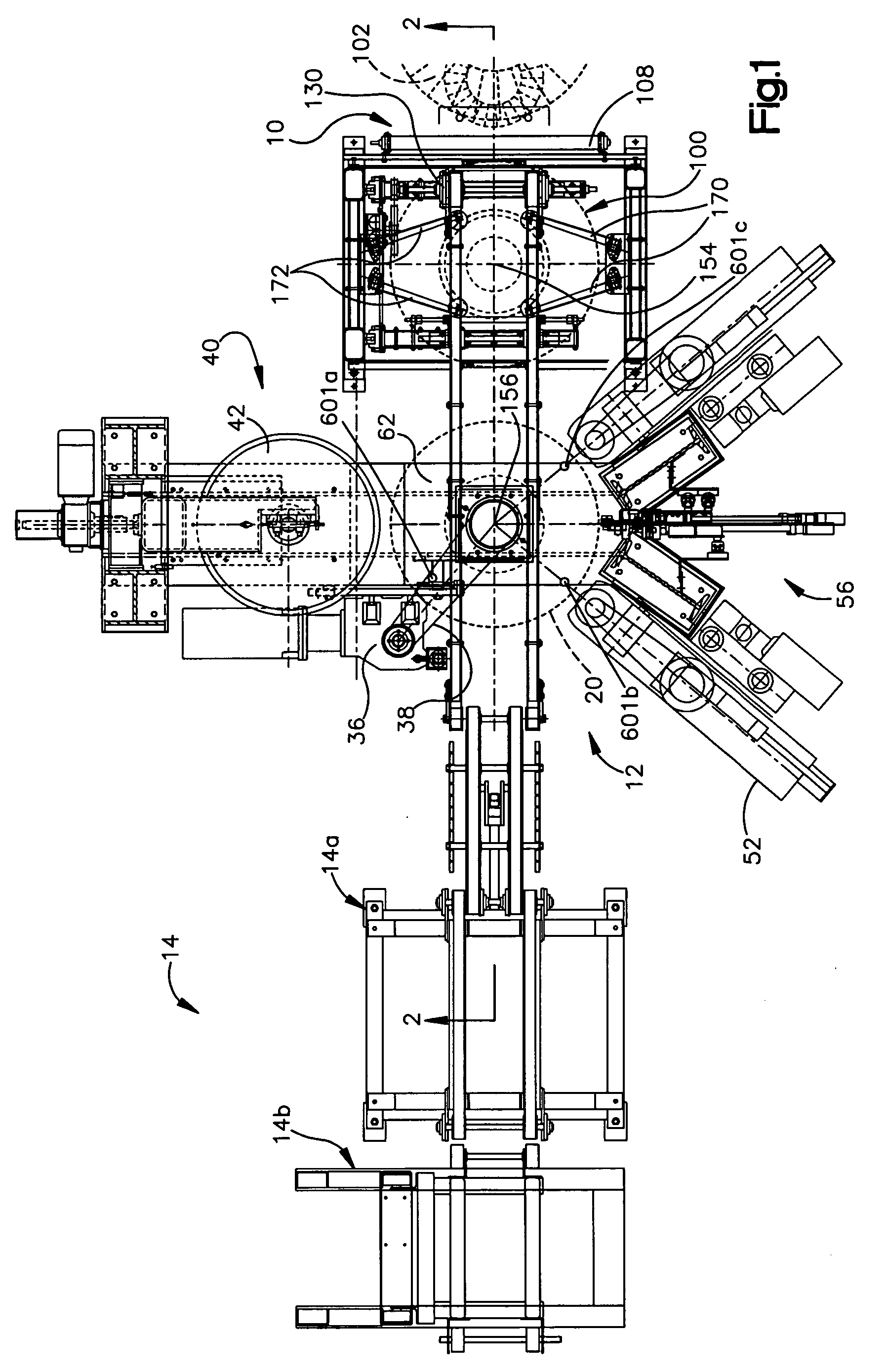
[0022]FIG. 1 illustrates, in plan view, the overall arrangement of a tire testing system which includes a tire position sensor subsystem constructed in accordance with the preferred embodiment of the invention. Except for the tire position sensor subsystem, the illustrated tire testing apparatus may be conventional. In particular, the illustrated apparatus (except for the tire position sensor subsystem) is more fully described in U.S. Pat. No. 6,016,695 entitled Tire Uniformity Testing System which is hereby incorporated by reference. Additional details of specific features of the tire uniformity testing system are described in U.S. Pat. No. 5,992,227 entitled Automatic Adjustable Width Chuck Apparatus For Tire Testing Systems, which is also hereby incorporated by reference.

[0023] To facilitate the explanation, it should be noted that reference characters, except for those reference characters referring to tire position sensors and related components correspond to the reference cha...


PUM


Abstract

A method and apparatus for chucking tires to be tested in a tire testing apparatus. A lower chuck assembly or spindle includes a lower rim that is engageable with a bead region of the tire to be tested. An upper chuck assembly includes an upper rim that is engageable with an upper bead region of the tire to be tested. The upper rim is reciprocally movable towards and away from the lower rim. A plurality of sensors associated with the movable rim monitors the closing distance between the upper rim and the side wall of the tire that is being chucked, during the chucking process. A controller controls the movement of the upper rim in response to the distance data obtained from the sensors. If the data obtained indicates that the tire is mispositioned on the lower rim, the controller will slow the rate of downward movement of the upper rim and reinitiate a chucking cycle if the upper rim reaches a predetermined lower position and the data from the distance sensors still indicates that the tire is not properly positioned. The sensors are mounted to an adjustable stripping mechanism that forms part of the upper chuck assembly. The positions of the sensors are adjusted as the tire strippers are adjusted.

Description

TECHNICAL FIELD [0001] The present invention relates generally to tire testing and, in particular, to an improved method and apparatus for clamping a tire between rim halves for testing purposes. It can serve as an improvement to the apparatus disclosed in U.S. Pat. No. 6,016,695 to Reynolds et al. BACKGROUND ART [0002] In currently available tire uniformity inspection machines, testing is fully automated. Tires are fed by conveyor to a test station where each tire is mounted upon two rim halves, inflated to a predetermined pressure and rotatably driven at a standard speed with its tread surface in abutting contact with the circumferential surface of a loadwheel. To mount a tire upon rim halves, a vertically movable upper rim is supported in the top of the machine and is mounted for movement towards and away from a lower rim mounted to a fixed, motor driven spindle mounted to the base of the machine. Other machines use a vertically movable lower rim that is supported in the base of ...

Claims


Application Information

Patent Timeline
IPC IPC(8): G01M17/02
CPCG01M17/022G01M17/021
Inventor CARGOULD, BARRYMULARCIK, BRADLEY S.NEIFERD, KEITH A.WNEK, JOSEPH A.
Owner MICRO POISE MEASUREMENT SYST
Why Eureka
Try Eureka