Packaging structure of electric storage cells

a technology of electric storage cells and packaging structures, which is applied in the direction of cell components, cell component details, electrochemical generators, etc., can solve the problems of reducing the power generation capacity of the power generation capacity, the effect of heat generated by the electric storage cell in use, and the temperature of the entire package is excessively increased,

Inactive Publication Date: 2007-08-16
FUJI JUKOGYO KK
View PDF4 Cites 55 Cited by
  • Summary
  • Abstract
  • Description
  • Claims
  • Application Information

AI Technical Summary

Problems solved by technology

Although the technology disclosed in Japanese Unexamined Patent Application Publication No. 2003-323874 is effective in stabilizing battery performance against vibration, the effects of heat generated by electric storage cells in use are unco

Method used


Image

  • Packaging structure of electric storage cells
  • Packaging structure of electric storage cells
  • Packaging structure of electric storage cells

Examples


Embodiment Construction

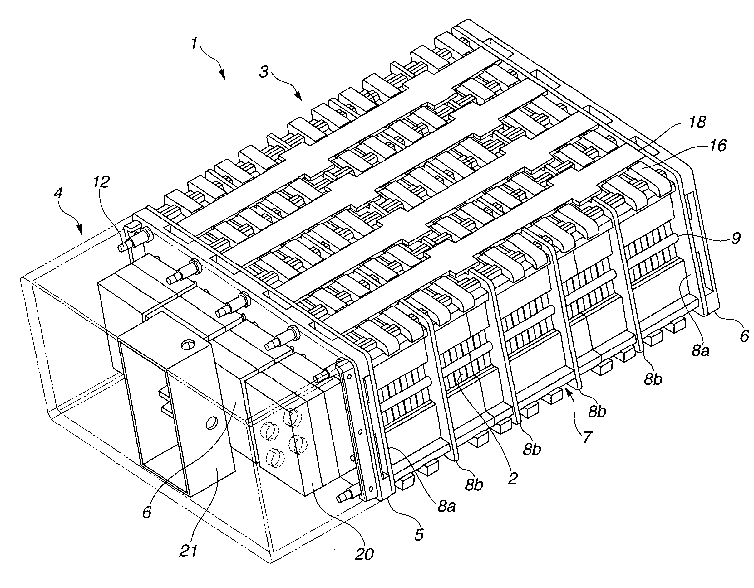
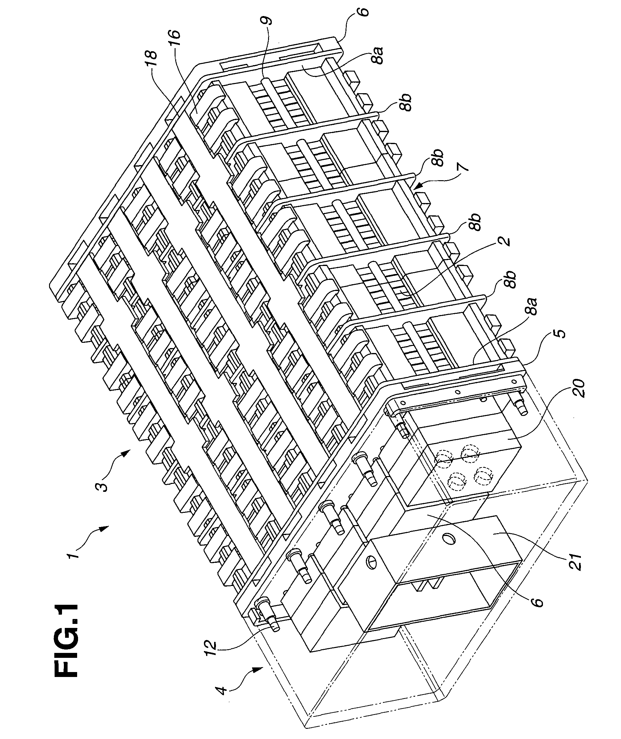
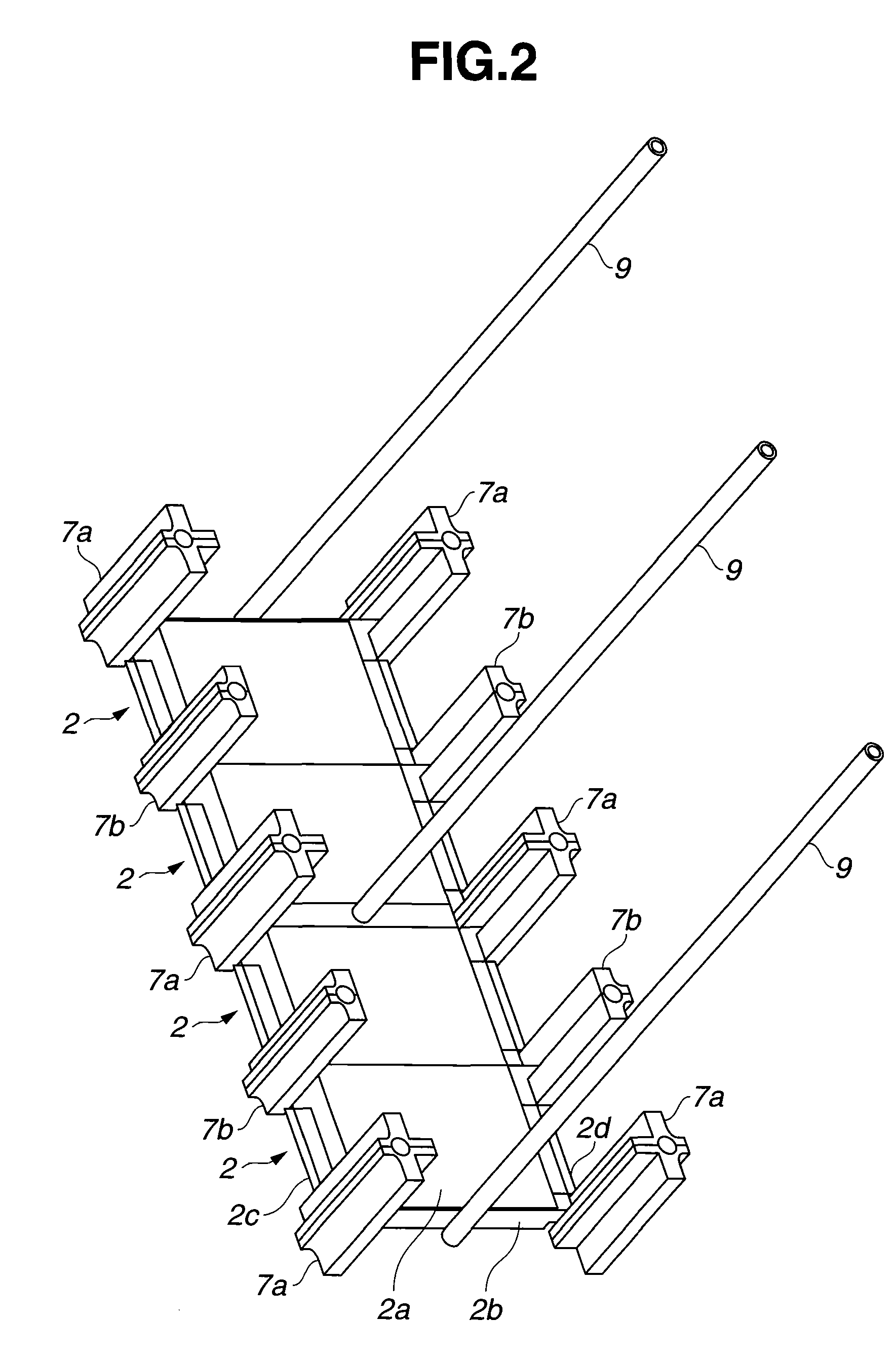
[0032] Embodiments of the present invention will now be described with reference to the drawings. FIGS. 1 to 15 are explanatory diagrams of showing an embodiment of the present invention. FIG. 1 is a general view of a power-supply unit including an electric storage package. FIG. 2 is an explanatory diagram of showing the layout of frame supports and heat-transferring pipes. FIG. 3 is an explanatory diagram of showing a front plate. FIG. 4 is an explanatory diagram of showing a rear plate. FIG. 5 is an explanatory diagram of showing a central cross section of the electric storage package in the longitudinal direction thereof. FIG. 6 is an explanatory diagram of showing a state of electric storage cells stacked via intermediate plates. FIG. 7 is an explanatory diagram of showing an example of connection between a heat-transferring sheet film and external heat-releasing members. FIG. 8 is an explanatory diagram of showing a state of the electric storage cells to which tab supports are ...


PUM


Abstract

Heat generated at electric storage cells are released using intermediate plates that are disposed at intervals of a predetermined number of layers in a lamination of the electric storage cells so as to retain the stacking surfaces of the electric storage cells therebetween, and at the same time, stacking surfaces of the cells are pressed with predetermined pressures by applying loads to the intermediate plates using wires provided for frame supports that are engaged with the intermediate plates. With this, the characteristics of the cells can be stabilized against both vibration and heat, and the performance of the entire package can be improved.

Description

CROSS REFERENCE TO RELATED APPLICATION [0001] This application is a continuation of PCT Application No. PCT / JP2005 / 019508 filed on Oct. 24, 2005, which in turn claims the benefit of Japanese Application No. 2004-315350 filed Oct. 29, 2004. The International Application was published in Japanese as WO 2006 / 046515 on May 4, 2006. The priority applications identified above are incorporated herein by reference.BACKGROUND OF THE INVENTION [0002] 1. Field of the Invention [0003] The present invention relates to packaging structures of electric storage cells including a plurality of flat electric storage cells that are stacked and packaged. [0004] 2. Description of the Related Art [0005] Recently, flat electric storage cells such as lithium-ion secondary batteries and electric double-layer capacitors having substantially flat and rectangular shapes have been in practical use, and have been seen as promising power sources for various devices due to their high energy density, easiness of siz...

Claims


Application Information

Patent Timeline
IPC IPC(8): H01M2/10H01G2/04H01G2/08H01M10/60H01M10/613H01M10/625H01M10/647H01M10/653H01M10/6554H01M10/6555H01M50/211H01M50/264H01M50/293H01M50/298
CPCH01G2/04Y02T10/7022H01G2/14H01G9/08H01G9/14H01G9/155H01M2/1072H01M10/0413H01M10/5004H01M10/5006H01M10/5016H01M10/5032H01M10/5046H01M10/5048H01M10/5055H01M10/5057H01M10/5065H01M10/5075Y02E60/13H01G2/106H01M10/625H01M10/615H01M10/647H01M10/6556H01M10/6551H01M10/6567H01M10/6552H01M10/6555H01M10/613H01M10/6562Y02T10/70Y02E60/10H01G11/78H01G11/82H01G11/18H01G11/12H01M50/293H01M50/264H01M50/211H01M50/298
Inventor SAKURAI
Owner FUJI JUKOGYO KK
Why Eureka
Try Eureka