Projection-type display devices with reduced speckle

a projection-type display and speckle technology, applied in the field of projection-type display devices, can solve the problems of reducing the luminous power consistency of the lamp with lamp age, affecting the luminous power consistency of the lamp, and the lifetime of the white light emitting lamp. achieve the effect of reducing the divergence of laser ligh

Inactive Publication Date: 2007-08-23
TRANSPACIFIC IMAGE
View PDF96 Cites 43 Cited by
  • Summary
  • Abstract
  • Description
  • Claims
  • Application Information

AI Technical Summary

Benefits of technology

[0007] The present invention relates to display devices that provide projection-type video output and use diode lasers to generate light. For example, one set of diode lasers may produce red light, while a second set produces blue light. One or more lenses may be employed to reduce divergence in the laser light generated by each diode laser. Optics are employed to expand laser light from its small generated or transmitted flux area to a size suitable for transmission onto an optical modulation device.
[0011] Another aspect of the invention relates to a redundant laser set to generate light. The laser set produces a desired amount of light, e.g., for a primary color. A redundant laser set includes more lasers than that needed to produce the desired amount of light. For example, a set of six lasers may only need five lasers to generate and emit the desired amount of light. The sixth laser allows failure of one laser in the set to not compromise operability of the entire set—and the display device. In addition, extra lasers in a laser set also allow the lasers to be cycled for heat purposes and to extend longevity of individual lasers in the set.
[0015] To reduce any speckle effects for a projected image cast by a projector onto of a non-specular surface, the present invention may decrease coherence of laser-generated light. In one embodiment, coherence reduction is accomplished by introducing a coherence diffuser in a light path of the laser light. Arranging the coherence diffuser in an unfocused light beam reduces both temporal and spatial coherence in the light. Arranging the rotating diffuser at the focus of a beam reduces only the temporal coherence while maintaining the spatial coherence.

Problems solved by technology

One problem with a white-light emitting lamp is lifetime.
Not only does a lamp burn out after about two thousand hours, but luminous power consistency often declines with lamp age.
The high price of currently available projectors—and the cost of replacement lamps—compromises market acceptance and projector sales.

Method used


Image

  • Projection-type display devices with reduced speckle
  • Projection-type display devices with reduced speckle
  • Projection-type display devices with reduced speckle

Examples


Embodiment Construction

[0028] The present invention will now be described in detail with reference to a few preferred embodiments thereof as illustrated in the accompanying drawings. In the following description, numerous specific details are set forth in order to provide a thorough understanding of the present invention. It will be apparent, however, to one skilled in the art, that the present invention may be practiced without some or all of these specific details. In other instances, well known process steps and / or structures have not been described in detail in order to not unnecessarily obscure the present invention.

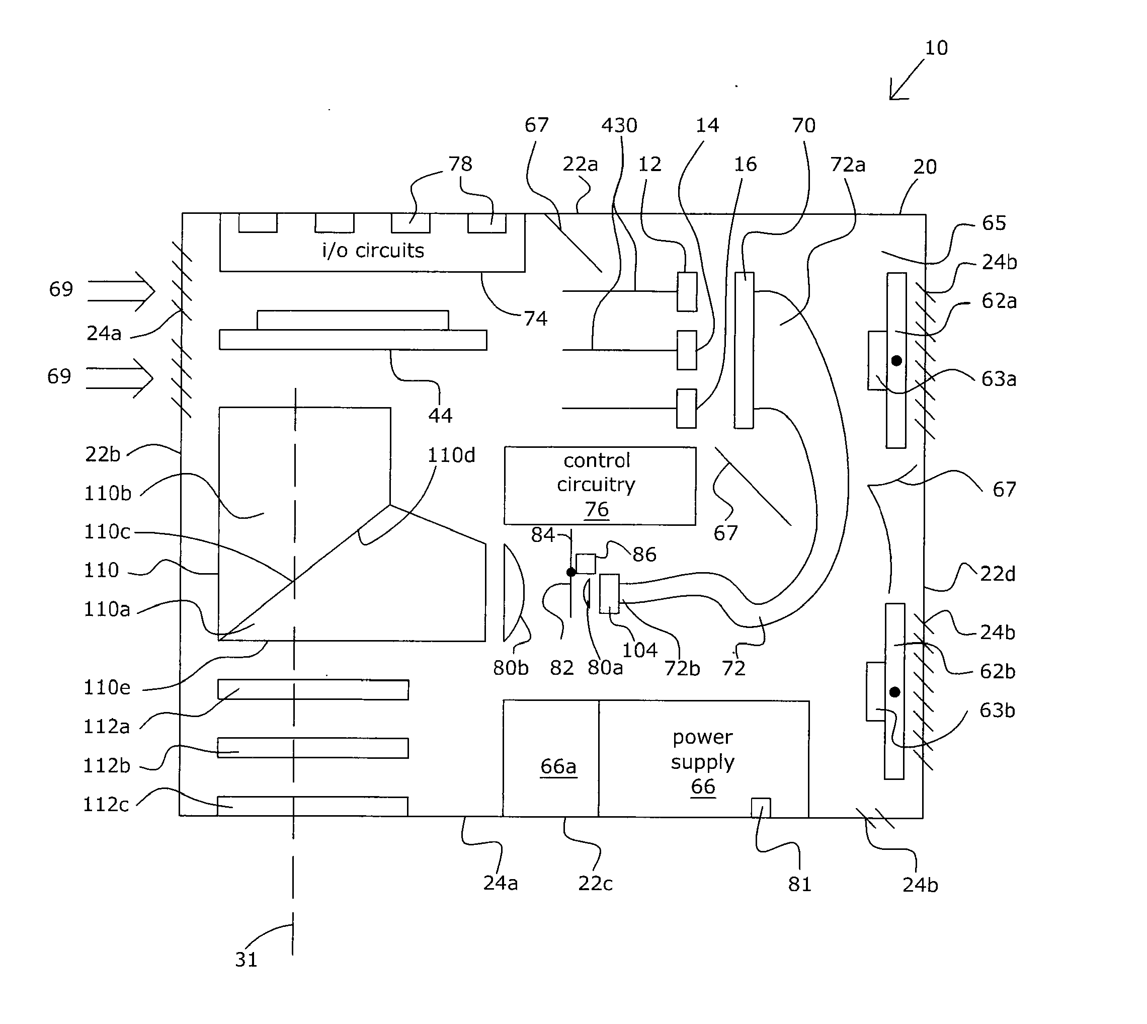
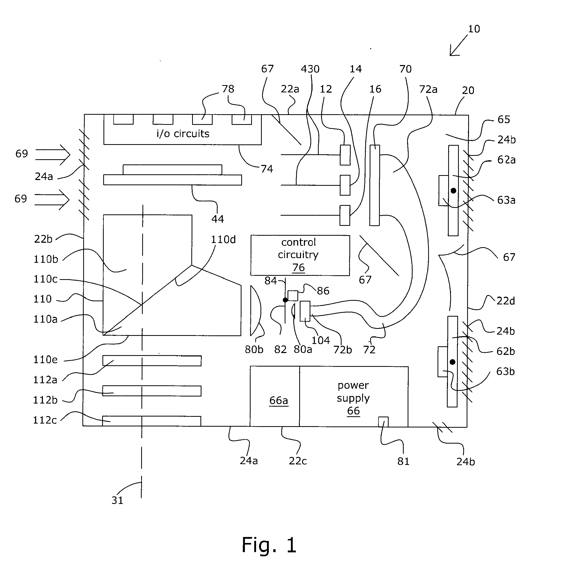
[0029]FIG. 1 illustrates a schematic of a projection type display device 10 in accordance with one embodiment of the present invention. Display device 10 is configured to produce and project a video image for display on a receiving surface. Display device 10 employs lasers to generate light. In one embodiment, display device 10 uses three sets of lasers—one for each primary color. As sho...


PUM


Abstract

Described herein are display devices that provide projection-type video output and use lasers to generate light. To reduce any speckle effects for a projected image cast by a projector onto of a non-specular surface, the present invention decreases coherence of the laser-generated light. Coherence reduction is accomplished by introducing a coherence diffuser in a light path of the laser light. Arranging the coherence diffuser in an unfocused light beam reduces both temporal and spatial coherence in the light. Arranging the rotating diffuser at the focus of a beam reduces only the temporal coherence while maintaining the spatial coherence.

Description

CROSS-REFERENCE TO RELATED APPLICATION [0001] This application claims priority under U.S.C. §120 from co-pending U.S. patent application Ser. No. 10 / 891,840, filed Jul. 15, 2004 and entitled, “POSITIONABLE PROJECTION DISPLAY DEVICES”, which is incorporated herein for all purposes; the patent application Ser. No. 10 / 891,840 also claimed under 35 U.S.C. §119(e) from co-pending U.S. Provisional Patent Application No. 60 / 487,868 filed Jul. 16, 2003, which is incorporated by reference herein for all purposes; the patent application Ser. No. 10 / 891,840 also claims priority under 35 U.S.C. §119(e) from co-pending U.S. Provisional Patent Application No. 60 / 487,871 filed Jul. 16, 2003, which is incorporated by reference herein for all purposes; the patent application Ser. No. 10 / 891,840 also claims priority under 35 U.S.C. §119(e) from co-pending U.S. Provisional Patent Application No. 60 / 487,691 filed Jul. 16, 2003, which is incorporated by reference herein for all purposes; the patent appl...

Claims


Application Information

Patent Timeline
Patent Type & Authority Applications(United States)
IPC IPC(8): G03B21/00G09G5/00H04N5/74
CPCG03B21/00G03B21/16H04N9/3141G03B21/005
Inventor PLUT, WILLIAM J.
Owner TRANSPACIFIC IMAGE
Why Eureka
Try Eureka