System and method for synchronizing audio-visual devices on a power line communications (PLC) network

a technology of audio-visual devices and plc networks, applied in powerline communications applications, wireless systems/telephones, instruments, etc., can solve the problems of insufficient synchronization accuracy, inability to overcome buffer depth dependence, and inability to provide synchronization, etc., to achieve sufficient synchronization accuracy, facilitate encoding and decoding activity, and reduce the effect of synchronization accuracy

Active Publication Date: 2006-04-06
SONY CORP +1
View PDF31 Cites 36 Cited by
  • Summary
  • Abstract
  • Description
  • Claims
  • Application Information

AI Technical Summary

Benefits of technology

[0013] The invention provides an apparatus and method for synchronizing the outputs of audio devices receiving audio data from a power line communications (PLC) network between streaming media devices. According to the invention, the server (or device operating temporarily, or permanently, in the role of a server) periodically broadcasts a system time clock (STC) value to decoders within clients on the PLC. The client decoder then adjusts its own STC value based on the one received. The clock divergence is preferably determined, such as averaged over a period of time, and the frequency of the system time clock (STC) in the client adjusted to minimize divergence allowing the client to remain in synchronization with the server. The reference clock value sent from the server is broadcast isochronously so that the devices receive the clock value with minimal delay and jitter.
[0017] It should also be recognized that clock oscillators typically have accuracies of about ten parts-per-million (10 ppm), wherein synchronization can exhibit a possible cumulative error of about 36 ms per hour. According to the present invention, a system time clock (STC) works in combination with a program clock reference (PCR) or a system clock reference (SCR) which is embedded within an MPEG stream at intervals, such as at 100-700 milliseconds. The decoder in the receiver adjusts its own system time clock (STC) to the SCR or PCR when it arrives. STC then starts counting up for each received clock. To determine the divergence between clocks, every time SCR or PCR arrives the change in the STC value is compared relative to the arriving SCR or PCR values. If STC gains more than the SCR or PCR values have gained, then this indicates that the STC clock signal for the decoder is running too fast (frequency is too high), wherein it can be slowed down appropriately. If STC gains less than the SCR or PCR values have gained, then this indicates that the STC clock signal for the decoder is running too slow, wherein it is speeded-up appropriately by changing its frequency. This method works well for keeping the clock rates of the sender and receiver synchronized so that the clock errors do not accumulate which facilitates encoding and decoding activity.
[0023] The video and audio data being communicated over the power line communications (PLC) network according to the invention comprises a digitally encoded format (i.e., MPEG) which is decoded at the receiving device. The system clock in each of the clients is adjusted to reduce absolute error as well as the difference in clock speeds as indicated by the divergence of time value from one received clock value to another.
[0027] Another aspect of the invention is to provide synchronization of audio devices utilizing an audio stream communicated over the PLC network so that the Haas effect is eliminated or significantly reduced.
[0029] Another aspect of the invention is to provide for adjusting the clock rates of client devices to reduce frequency divergence from the server clock frequency.

Problems solved by technology

A time stamping mechanism exists for use with MPEG streams, however, it cannot provide sufficient synchronization accuracy when audio is output to multiple devices over a PLC network.
The synchronization, however, cannot overcome dependence on buffer depth and the delays associated with communicating clock information asynchronously between the server and clients.

Method used


Image

  • System and method for synchronizing audio-visual devices on a power line communications (PLC) network
  • System and method for synchronizing audio-visual devices on a power line communications (PLC) network
  • System and method for synchronizing audio-visual devices on a power line communications (PLC) network

Examples


Embodiment Construction

[0048] Referring more specifically to the drawings, for illustrative purposes the present invention is embodied in the apparatus and method generally shown in FIG. 1 through FIG. 8. It will be appreciated that the apparatus may vary as to configuration and as to details of the parts, and that the method may vary as to the specific steps and sequence, without departing from the basic concepts as disclosed herein.

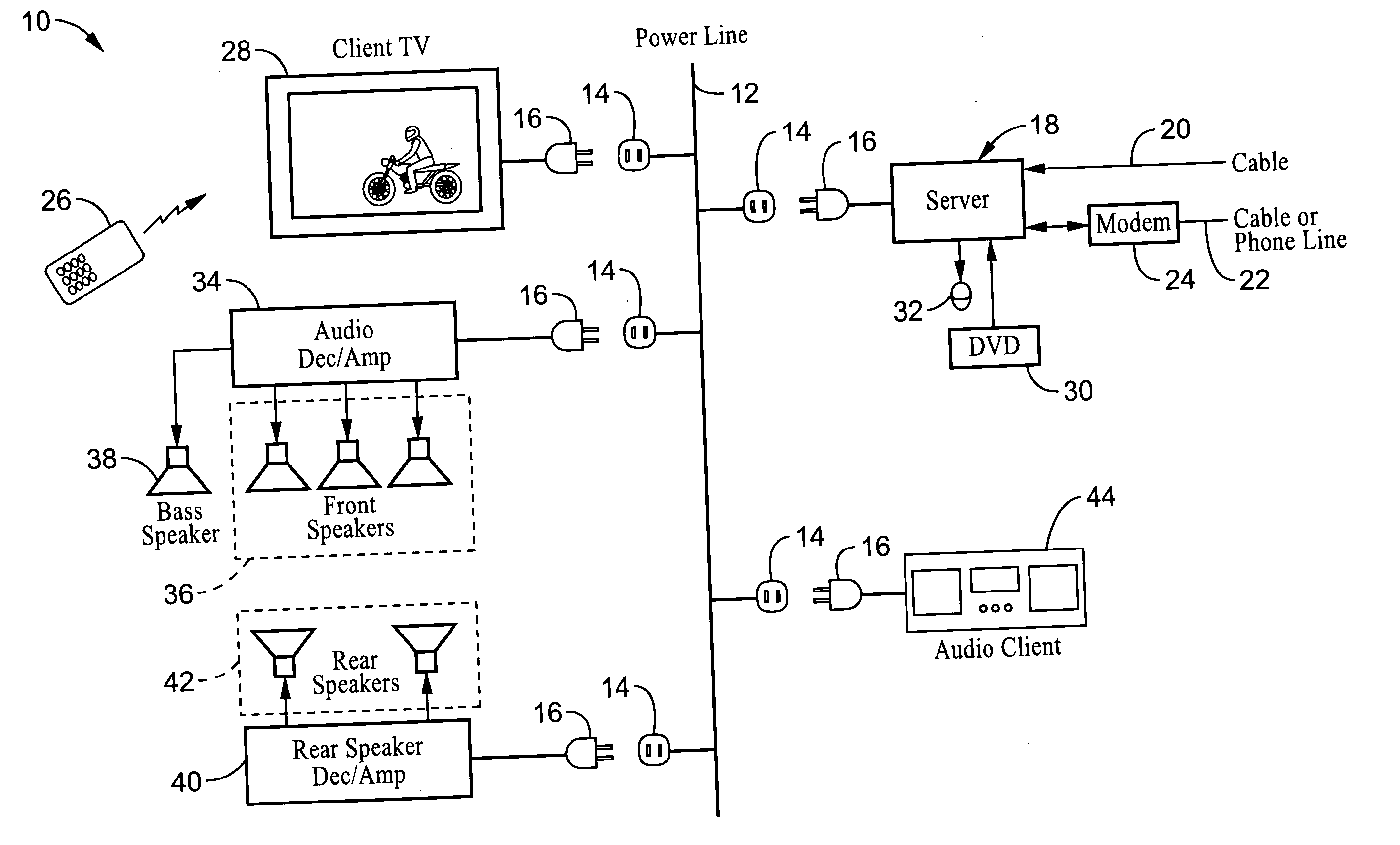
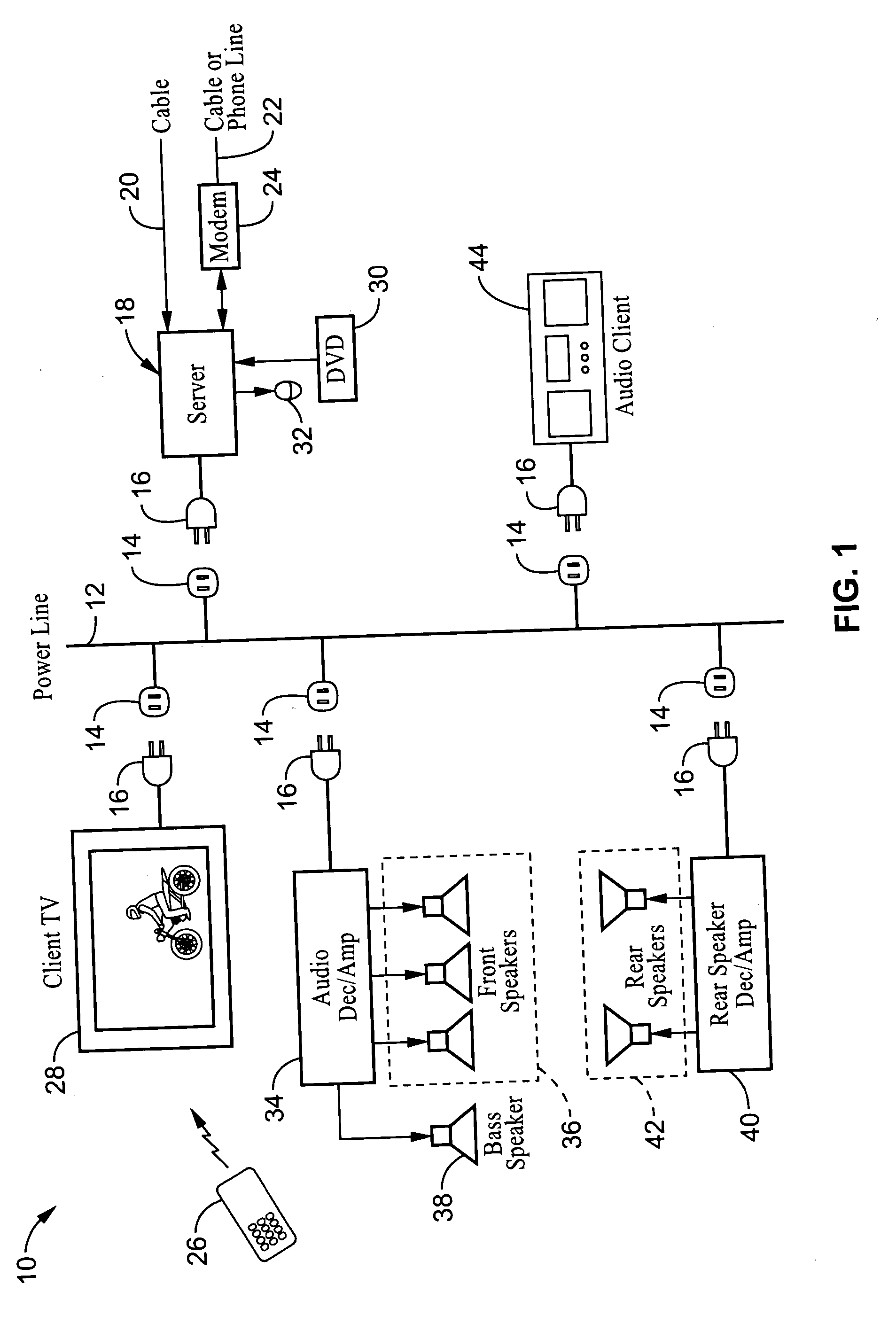
[0049] The present invention provides mechanisms for synchronizing media being output by devices coupled to the power line communications (PLC) network. In particular, the enhanced accuracy of synchronization is particularly well suited for systems in which an audio stream shared over the PLC network is being output from multiple devices.

[0050]FIG. 1 illustrates an example of audio-video connectivity 10 in which a power-line communications (PLC) network 12 having outlets 14 interconnects a number of audio and video devices having power plugs 16 which are coupled to outlets ...


PUM


Abstract

A method and apparatus for synchronizing streaming media devices within a PLC network. Output synchronization errors exceeding ˜30 ms become noticeable when multiple streaming media devices are outputting an audio stream. The present invention provides a system and method for isochronously sending periodic reference clocks from a master device to client devices coupled to the PLC network. The client devices set their clocks based on the reference clock. In addition the clients adjust their system clock time base in response to the average divergence of the system clock with the reference clock, or a count of the number of clocks between beacon frames. In this way the client clock is adjusted to closely track the server clock so that synchronization is maintained between each of the devices. Streaming audio shared between servers and client devices is thus output across the network with high fidelity due to the accurate synchronization.

Description

CROSS-REFERENCE TO RELATED APPLICATIONS [0001] This application claims priority from U.S. provisional application Ser. No. 60 / 616,073 filed on Oct. 4, 2004, incorporated herein by reference in its entirety.STATEMENT REGARDING FEDERALLY SPONSORED RESEARCH OR DEVELOPMENT [0002] Not Applicable INCORPORATION-BY-REFERENCE OF MATERIAL SUBMITTED ON A COMPACT DISC [0003] Not Applicable NOTICE OF MATERIAL SUBJECT TO COPYRIGHT PROTECTION [0004] A portion of the material in this patent document is subject to copyright protection under the copyright laws of the United States and of other countries. The owner of the copyright rights has no objection to the facsimile reproduction by anyone of the patent document or the patent disclosure, as it appears in the United States Patent and Trademark Office publicly available file or records, but otherwise reserves all copyright rights whatsoever. The copyright owner does not hereby waive any of its rights to have this patent document maintained in secre...

Claims


Application Information

Patent Timeline
Patent Type & Authority Applications(United States)
IPC IPC(8): H04L7/00
CPCH04B1/66H04B3/542H04B2203/5408H04B2203/5441H04B2203/5445H04B2203/545H04B2203/5483H04J3/0664H04N21/4147H04N21/42646H04N21/4302H04N21/4305
Inventor IWAMURA, RYUICHI
Owner SONY CORP
Why Eureka
Try Eureka