Reducing back-reflection in laser micromachining systems

Inactive Publication Date: 2012-06-21
ELECTRO SCI IND INC
View PDF7 Cites 28 Cited by
  • Summary
  • Abstract
  • Description
  • Claims
  • Application Information

AI Technical Summary

Benefits of technology

[0012]Disclosed systems and methods reduce or prevent back-reflections in a laser processing system. In one embodiment, a system includes a laser source to generate an incident laser beam, a laser beam output to direct the incident laser beam toward a work surface along a beam path, and a spatial filter. The system further includes a beam expander to expand a diameter of the incident laser beam received through the spatial filter, and a sc

Problems solved by technology

Laser back-reflection may cause laser instability or damage to certain types of lasers.
If such reflections are not properly blocked, e.g., if there is a return path for such reflections to couple back into an output fiber, it is possible that both the output fiber and gain fibers may be damaged.
Further, a seed laser may be damaged in a high-power

Method used


Image

  • Reducing back-reflection in laser micromachining systems
  • Reducing back-reflection in laser micromachining systems
  • Reducing back-reflection in laser micromachining systems

Examples


Embodiment Construction

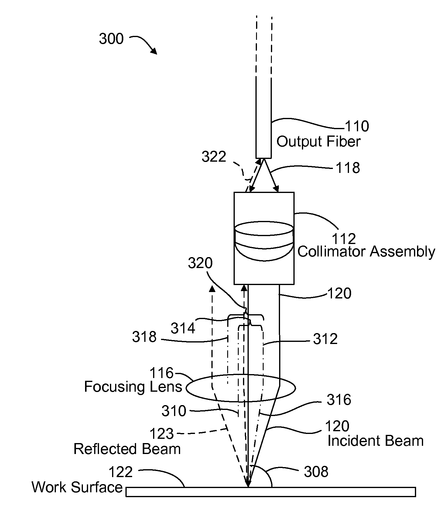
[0030]Various systems and methods described herein reduce or prevent back-reflections from coupling into an output fiber of a laser processing system without using bulky and / or expensive isolators. In one embodiment, a focusing lens is placed in the beam path at an offset distance from the beam propagation axis so as to impart a non-vertical “angle-of-attack” to the incident beam with respect to the work surface. This provides a spatial separation between incident and reflected beam paths without tilting the entire beam delivery subsystem with respect to the work surface. In one embodiment, an aperture further blocks the back-reflected laser beam from reaching the output fiber. In addition, or in another embodiment, a secondary beam positioner scans an incident laser beam across the focusing lens at an offset from the focusing lens's primary axis such that a scanning focal plane is substantially parallel to the work surface.

[0031]Other embodiments disclosed herein effectively reduce...


PUM

PropertyMeasurementUnit
Angleaaaaaaaaaa
Poweraaaaaaaaaa
Sizeaaaaaaaaaa

Abstract

Systems and methods reduce or prevent back-reflections in a laser processing system. A system includes a laser source to generate an incident laser beam, a laser beam output to direct the incident laser beam toward a work surface along a beam path, and a spatial filter. The system further includes a beam expander to expand a diameter of the incident laser beam received through the spatial filter, and a scan lens to focus the expanded incident laser beam at a target location on a work surface. A reflected laser beam from the work surface returns through the scan lens to the beam expander, which reduces a diameter of the reflected beam and increases a divergence angle of the reflected laser beam. The spatial filter blocks a portion of the diverging reflected laser beam from passing through the aperture and returning to the laser beam output.

Description

TECHNICAL FIELD[0001]This disclosure relates to processing materials with lasers. In particular, this disclosure relates to reducing laser beam back-reflection.BACKGROUND INFORMATION[0002]Generally, certain lasers may be sensitive to optical feedback from a laser beam reflected back to the laser from a work surface. Laser back-reflection may cause laser instability or damage to certain types of lasers. For example, fiber lasers are typically very sensitive to back-reflections from a work surface. If such reflections are not properly blocked, e.g., if there is a return path for such reflections to couple back into an output fiber, it is possible that both the output fiber and gain fibers may be damaged. Further, a seed laser may be damaged in a high-power master oscillator fiber amplifier device by reflected light that is amplified on its way back to the seed laser. In many laser processing systems, such as laser micromachining systems, it is therefore desirable to prevent such back-...

Claims


Application Information

Patent Timeline
IPC IPC(8): B23K26/06H01S3/10
CPCH01S3/0064B23K26/0656B23K26/066
Inventor LI, GUANGYUALPAY, MEHMET E.
Owner ELECTRO SCI IND INC
Why Eureka
Try Eureka