Method and apparatus for unifying light beams

Inactive Publication Date: 2002-05-02
SOLODOVNIKOV VLADIMIR VADIMOVICH +1
View PDF0 Cites 33 Cited by
  • Summary
  • Abstract
  • Description
  • Claims
  • Application Information

AI Technical Summary

Problems solved by technology

One of the problems of great importance in laser engineering consists in providing coherent light sources having high brightness and high power output density wherein such light could be coupled e.g. into an optical fiber of 50 .mu.m diameter.
Problems th

Method used


Image

  • Method and apparatus for unifying light beams
  • Method and apparatus for unifying light beams
  • Method and apparatus for unifying light beams

Examples


Embodiment Construction

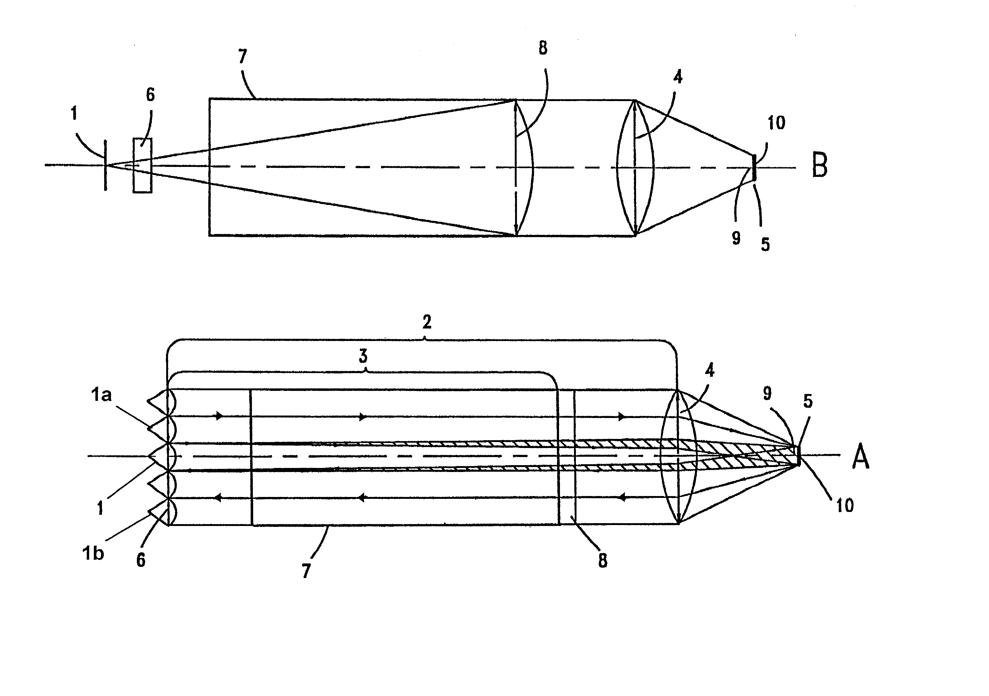
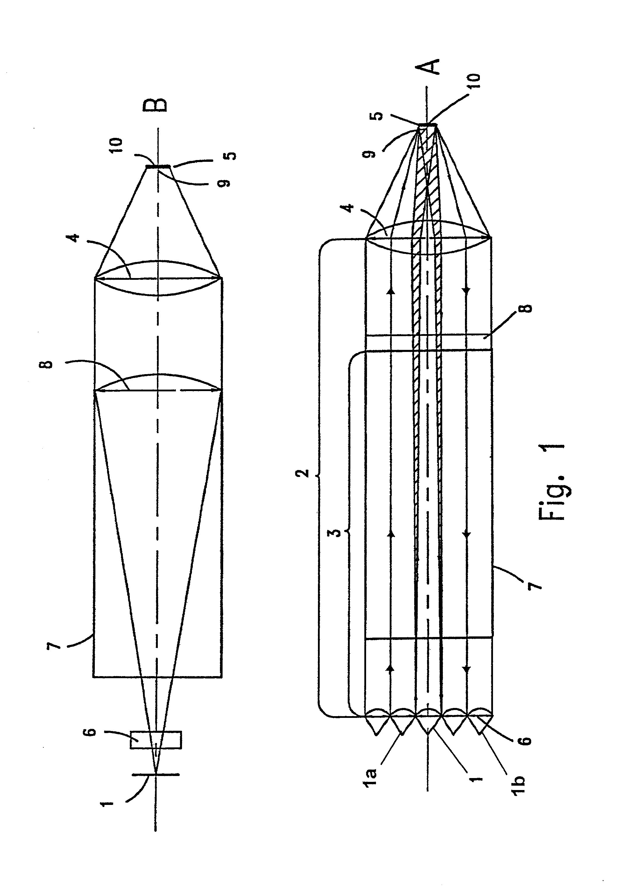
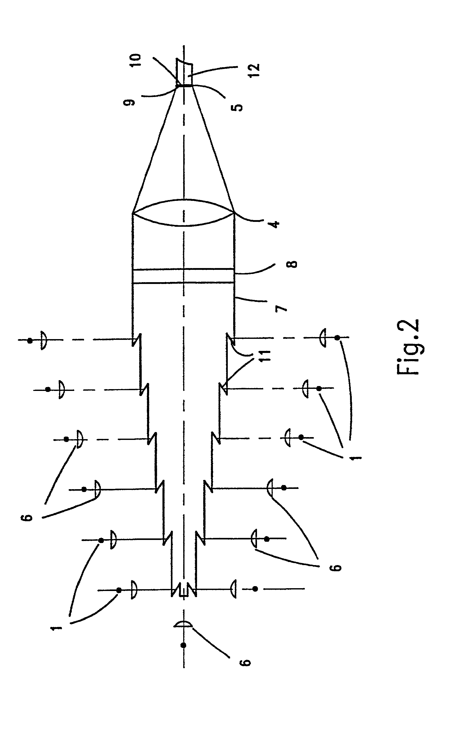
[0018] The invention aims to provide a light-emitting adder or light unifier, which comprises a plurality of light sources, particularly laser sources, each of which emits a beam having a rectangular cross-section in a plane perpendicular to the source optical axis, viz. perpendicular to the direction of propagation of the emitted beam. Said cross-section has a long side and a short side. The long side will be called herein the longitudinal side and the short side will be called the transverse side. In a system of Cartesian coordinates, the X axis will be considered to be parallel to the longitudinal direction, the Y axis to the transverse direction, and the Z axis to the direction of propagation of the beam. In rectangular laser beams, the ratio of the long side of the rectangular cross-section to the short side is high, e.g., 20 / 1 or 120 / 1. Beams of such cross-section are produced by laser sources well known in the art, for instance SDL-6370-A, SDL-6380-A, SDL-6380-L-2, S-915-500C...


PUM


Abstract

A light unifier, which comprises a plurality of light sources, particularly laser diodes, emitting parallel light beams of a rectangular cross-section, for focusing the light energy of all the beams onto a target area through beam-shaping means, which comprises transverse collimators, means for juxtaposing the emitted beams to form a unified beam, a longitudinal collimator for longitudinally collimating the unified beam, and means for focusing it onto the target area. The light beams have a transverse and a longitudinal divergence and the ratio of the transverse divergence to the longitudinal divergence is higher than 1. The transverse collimators are placed at such a distance from the sources that, at the point at which the beams reach them, the sum of the short sides of the beams is equal to the long side of each of them at the point at which they reach the longitudinal collimator. The number of light sources is such as to permit to obtain a unified beam that has a square cross-section and the same divergence on all its sides. Two groups of laser diodes may be arranged in parallel or mutually perpendicular planes and the unified beams produced by them are focused together onto the target area.

Description

SPECIFICATION[0001] This application is a continuation-in-part of application Ser. No. 09 / 783,475 filed Feb. 14, 2001. This application is also a continuation-in-part of PCT / RU / 00363 filed Nov. 4, 1998 designating the U.S. and published in Russian on May 11, 2000 as WO 00 / 27002. This application additionally claims priority from Israeli Patent Application No. 140,386 filed Dec. 18, 2000[0002] The present invention relates to a method and a device for unifying the beams produced by light sources, particularly laser diodes, so as to obtain a unified beam having high power, high brightness and high output density, adapted to be focused especially on optical fiber cross-sections.DESCRIPTION OF THE PRIOR ART[0003] One of the problems of great importance in laser engineering consists in providing coherent light sources having high brightness and high power output density wherein such light could be coupled e.g. into an optical fiber of 50 .mu.m diameter.[0004] Known are various structures...

Claims


Application Information

Patent Timeline
IPC IPC(8): G02B27/09H01S3/00H01S5/00H01S5/40
CPCG02B27/09H01S5/4025H01S5/005H01S3/005
Inventor SOLODOVNIKOV, VLADIMIR VADIMOVICHLAVROV, ANATOLY FEDOROVICH
Owner SOLODOVNIKOV VLADIMIR VADIMOVICH
Why Eureka
Try Eureka