Method and apparatus for delivering an intervertebral disc implant

a technology of intervertebral discs and implants, which is applied in the field of spinal implants, can solve the problems of disc shrinkage and rupture of degenerated discs, prone to injury and degeneration of intervertebral discs, and herniated discs,

Inactive Publication Date: 2007-08-23
WARSAW ORTHOPEDIC INC
View PDF99 Cites 120 Cited by
  • Summary
  • Abstract
  • Description
  • Claims
  • Application Information

AI Technical Summary

Problems solved by technology

It is known that intervertebral discs are prone to injury and degeneration.
For example, herniated discs are common, and typically occur when normal wear, or exceptional strain, causes a disc to rupture.
Degenerative disc disease typically results from the normal aging process, in which the tissue gradually looses its natural water and elasticity, causing the degenerated disc to shrink and possibly rupture.
One problem associated with such implants is that they require a relatively large hole to be cut in the disc annulus to allow introduction of the implant.
This complicates the procedure, adding surgical time and cost, and leaving a less sound annulus when the procedure is complete.
Moreover, the devices heretofore used to deliver a spinal disc implant have been difficult load and operate.

Method used


Image

  • Method and apparatus for delivering an intervertebral disc implant
  • Method and apparatus for delivering an intervertebral disc implant
  • Method and apparatus for delivering an intervertebral disc implant

Examples


example 1

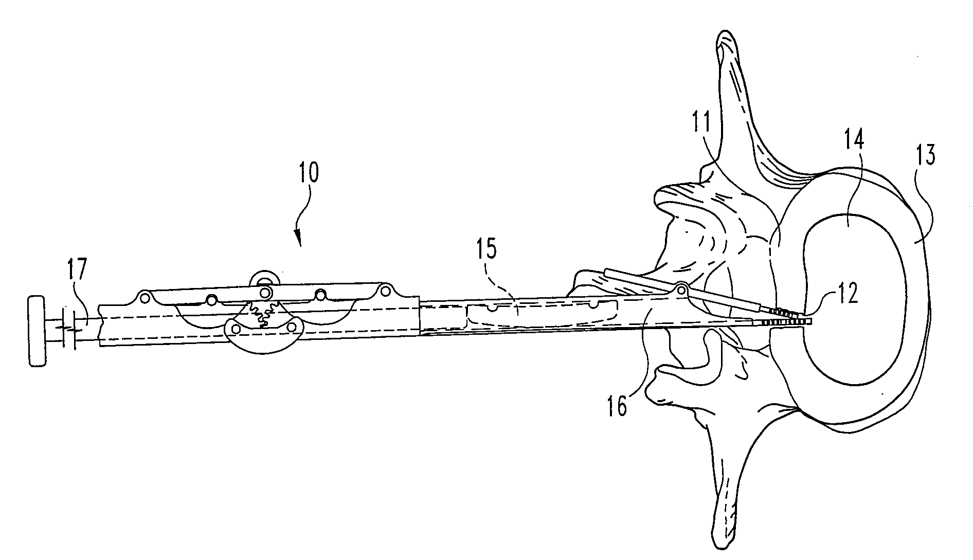
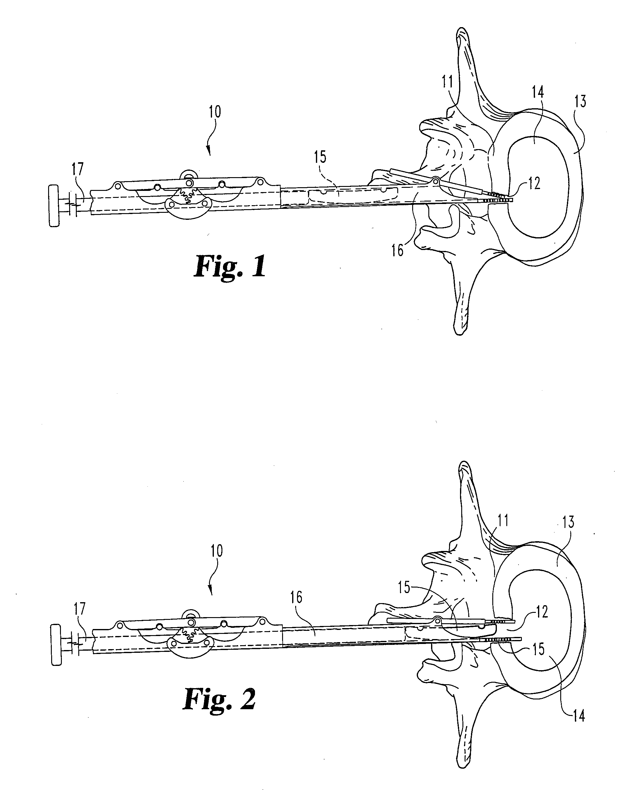
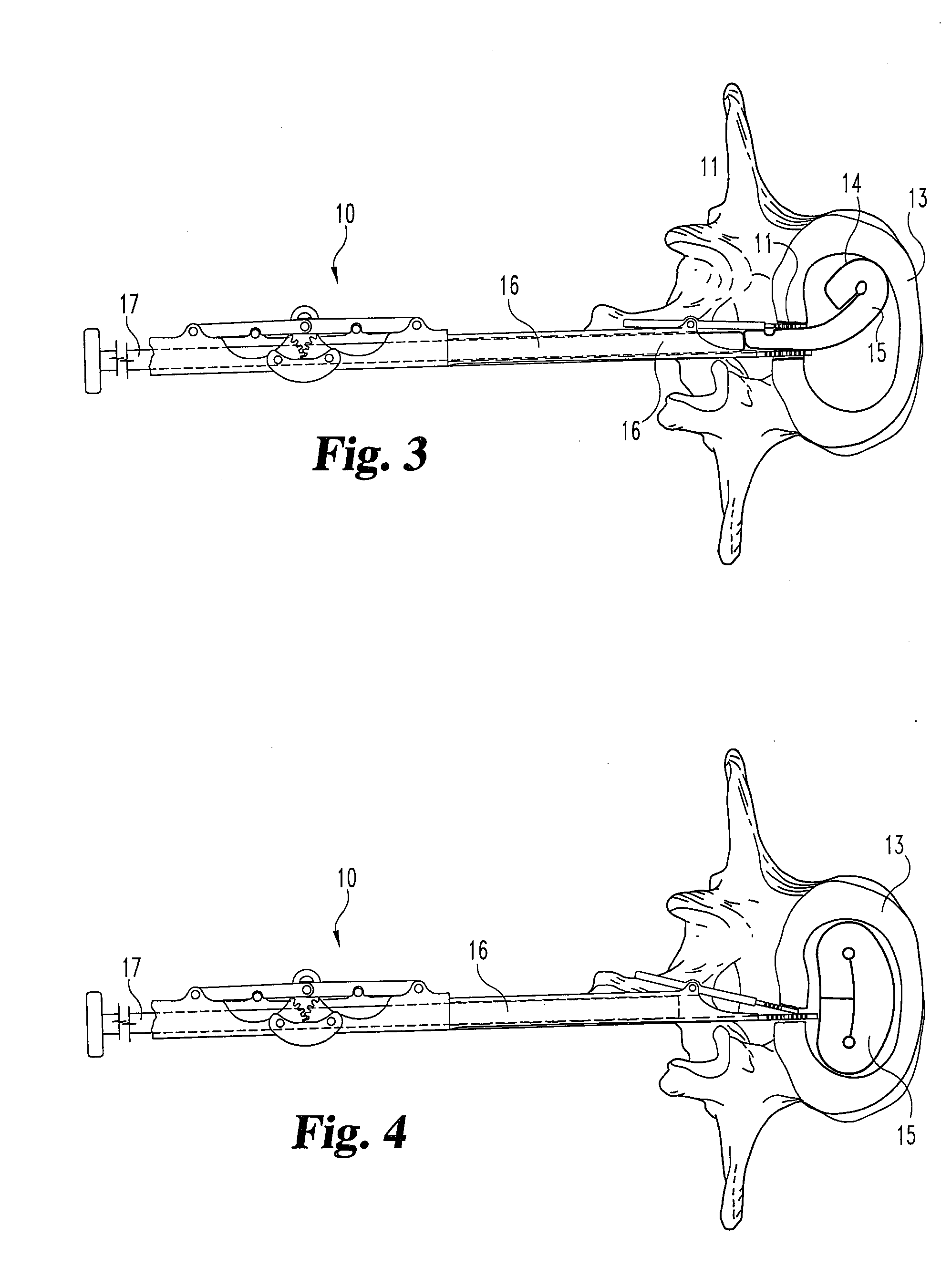
[0199] A medical patient is treated to replace a damaged or degenerated lumbar intervertebral disc nucleus using the procedure described below.

[0200] A / P and M / L radiographs are obtained to determine the size and shape of the affected level. The largest implant that can be accommodated by patient anatomy without overdistraction is selected, choosing among implants having footprints of 19 mm×23 mm to 22 mm×27 mm, and a height of between 6 mm and 14 mm. It is important to select the tallest device that can be accommodated by the interbody space. Excessive annulus laxity may cause non-central seating of the implant. X-ray templates are used to determine whether a small or large device footprint should be used, as are AP and ML implant outlines to determine the appropriate height.

[0201] The patient is placed in a direct prone positioned on the operating table. Bolster appropriately to maintain lumbar lordosis. C-arm fluoroscopy is not absolutely necessary for the procedure, but is pre...


PUM

PropertyMeasurementUnit
angleaaaaaaaaaa
angleaaaaaaaaaa
inner diameteraaaaaaaaaa

Abstract

A method for implanting a prosthetic spinal disc nucleus in an intervertebral disc nucleus space includes: (a) providing a disc nucleus implant instrument having a passageway for passing a prosthetic disc nucleus, and a dilator for dilating an opening in a disc annulus; (b) providing a prosthetic disc nucleus having a first configuration and a second configuration, where the first configuration presents a first cross-sectional size and said second configuration presents a second cross-sectional size, with the first cross-sectional size being larger than the second cross-sectional size; (c) making a hole in the annulus of a disc receiving the prosthetic disc nucleus, with the hole having an undilated size that is smaller than the first cross-sectional size of said prosthetic disc nucleus; (d) providing the prosthetic disc nucleus in its second configuration in the passageway of said disc nucleus implant instrument; (e) introducing the dilator of the disc nucleus implant instrument into the hole in the disc annulus while said hole is not fully dilated; (f) causing the dilator to dilate the hole in the disc annulus; (g) passing the prosthetic disc nucleus through the dilator and into the disc nucleus space while the disc annulus is dilated and the prosthetic disc nucleus is in its second configuration; (h) withdrawing the disc nucleus implant instrument and allowing the disc annulus to return to a size smaller that its dilated size; and (i) causing or allowing the prosthetic disc nucleus to assume its first configuration. The disc nucleus implant instrument may also include an activator for causing the dilator to dilate.

Description

CROSS-REFERENCE TO RELATED APPLICATIONS [0001] This application is a divisional application of pending U.S. patent application Ser. No. 10 / 717,687, filed Nov. 20, 2003, which is a continuation-in-part of pending U.S. patent application Ser. No. 09 / 943,441, filed Aug. 30, 2001, and of pending U.S. patent application Ser. No. 10 / 459,630, filed Jun. 11, 2003, both of which are continuations-in-part of U.S. patent application Ser. No. 09 / 650,525, filed Aug. 30, 2000. All of the foregoing are hereby incorporated by reference into this application in their entirety.FIELD OF THE INVENTION [0002] The present invention relates generally to methods and instruments for delivering a spinal implant, and more particularly to methods and instruments for implanting material to augment, repair, or replace an intervertebral disc nucleus. BACKGROUND OF THE INVENTION [0003] The intervertebral disc functions to stabilize the spine and to distribute forces between vertebral bodies. A normal disc includes...

Claims


Application Information

Patent Timeline
Patent Type & Authority Applications(United States)
IPC IPC(8): A61F2/44A61B17/88A61F2/46A61B17/56A61B17/02A61F2/00A61F2/02A61F2/28A61F2/30A61L27/00
CPCA61B2017/0256A61F2310/00023A61F2/30965A61F2/441A61F2/442A61F2/4611A61F2002/2817A61F2002/30056A61F2002/30062A61F2002/3008A61F2002/30092A61F2002/30133A61F2002/30179A61F2002/302A61F2002/30224A61F2002/30291A61F2002/30563A61F2002/30596A61F2002/30604A61F2002/30677A61F2002/30719A61F2002/30827A61F2002/30838A61F2002/30891A61F2002/30906A61F2002/30909A61F2002/30925A61F2002/30957A61F2002/4415A61F2002/444A61F2002/4495A61F2002/4622A61F2002/4627A61F2002/4628A61F2210/0004A61F2210/0014A61F2230/0015A61F2230/0058A61F2230/0065A61F2230/0069A61F2230/0091A61F2250/0032A61F2250/0092A61F2250/0098A61F2310/00017A61F2/30767A61F2002/30594
Inventor TRIEU, HAI H.JUSTIS, JEFF R.LIM, ROY
Owner WARSAW ORTHOPEDIC INC
Why Eureka
Try Eureka