Spinal disc annulus augmentation

a technology of intervertebral discs and annulus, which is applied in the field of intervertebral disc annulus augmentation, can solve the problems of localized bulge, chemical irritation and inflammation of nerve roots, and the posterior protrusion of intervertebral discs are particularly problematic, so as to prevent the consequences and problems associated, the effect of augmentation of the annulus of the intervertebral dis

Inactive Publication Date: 2006-11-30
SAAL JEFFREY ALAN +1
View PDF12 Cites 15 Cited by
  • Summary
  • Abstract
  • Description
  • Claims
  • Application Information

AI Technical Summary

Benefits of technology

[0010] The present invention provides devices for augmenting the intervertebral disc annulus. The devices are particularly useful in treating, delaying or preventing the consequences and problems associated of degeneration of the disc. The invention further includes methods directed to the minimally invasive implantation of one or more devices of the present invention within an intervertebral disc annulus.

Problems solved by technology

Such fissures may progress to larger tears which allow the gelatinous material of the nucleus to migrate out of the nucleus and into the outer aspects of the annulus which may cause a localized bulge.
In the event of annulus rupture, the nuclear material may escape, causing chemical irritation and inflammation of the nerve roots.
Posterior protrusions of intervertebral discs are particularly problematic since the nerve roots are posteriorly positioned relative to the intervertebral discs.
Impingement or irritation of the nerve roots not only results in pain in the region of the back adjacent the disc, but may also cause radicular pain such as sciatica.
Nerve compression and inflammation may also lead to numbness, weakness, and in late stages, paralysis and muscle atrophy, and / or bladder and bowel incontinence.
This can result in deterioration of facet cartilage and ultimately osteoarthritis and pain in the facet joints.
A common treatment for a disc protrusion is discetomy, a procedure wherein the protruding portion of the disc is surgically removed and the weakened or ruptured portion of the annulus is repaired Discectomy procedures have an inherent risk since the portion of the disc to be removed is immediately adjacent the nerve root and any damage to the nerve root is clearly undesirable.
Furthermore, discectomy procedures are not always successful in the long term as the annulus fibrosis has been shown to have limited healing capacity increasing the risk of re-herniation.
A compromised annulus may lead to accelerated disc degeneration which may require spinal interbody fusion or total disc replacement.

Method used


Image

  • Spinal disc annulus augmentation
  • Spinal disc annulus augmentation
  • Spinal disc annulus augmentation

Examples


Embodiment Construction

[0034] Before the subject devices, systems and methods are described, it is to be understood that this invention is not limited to particular embodiments described, as such may, of course, vary. It is also to be understood that the terminology used herein is for the purpose of describing particular embodiments only, and is not intended to be limiting, since the scope of the present invention will be limited only by the appended claims.

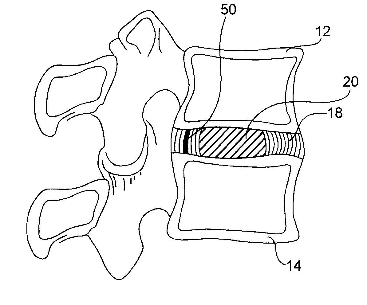
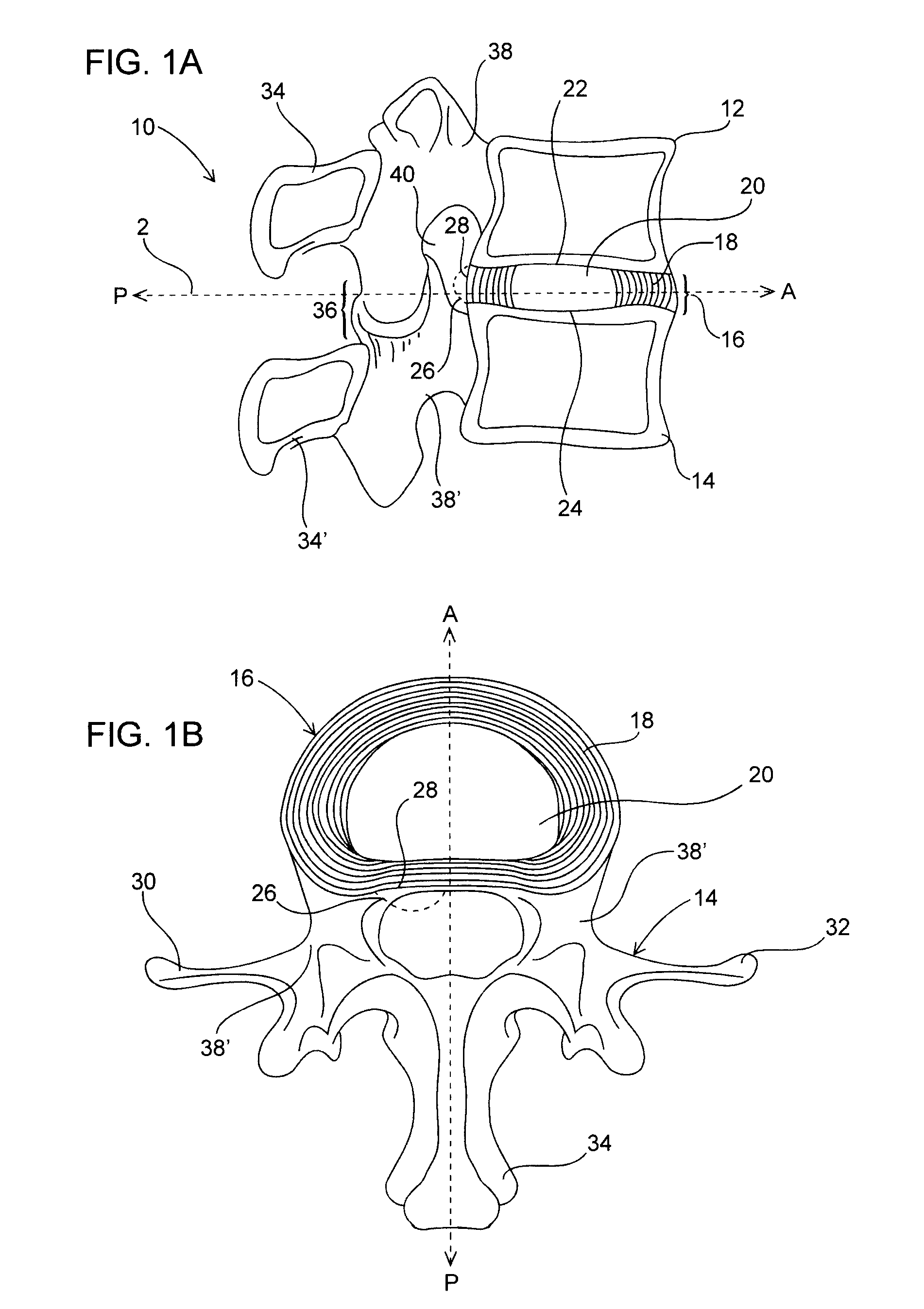
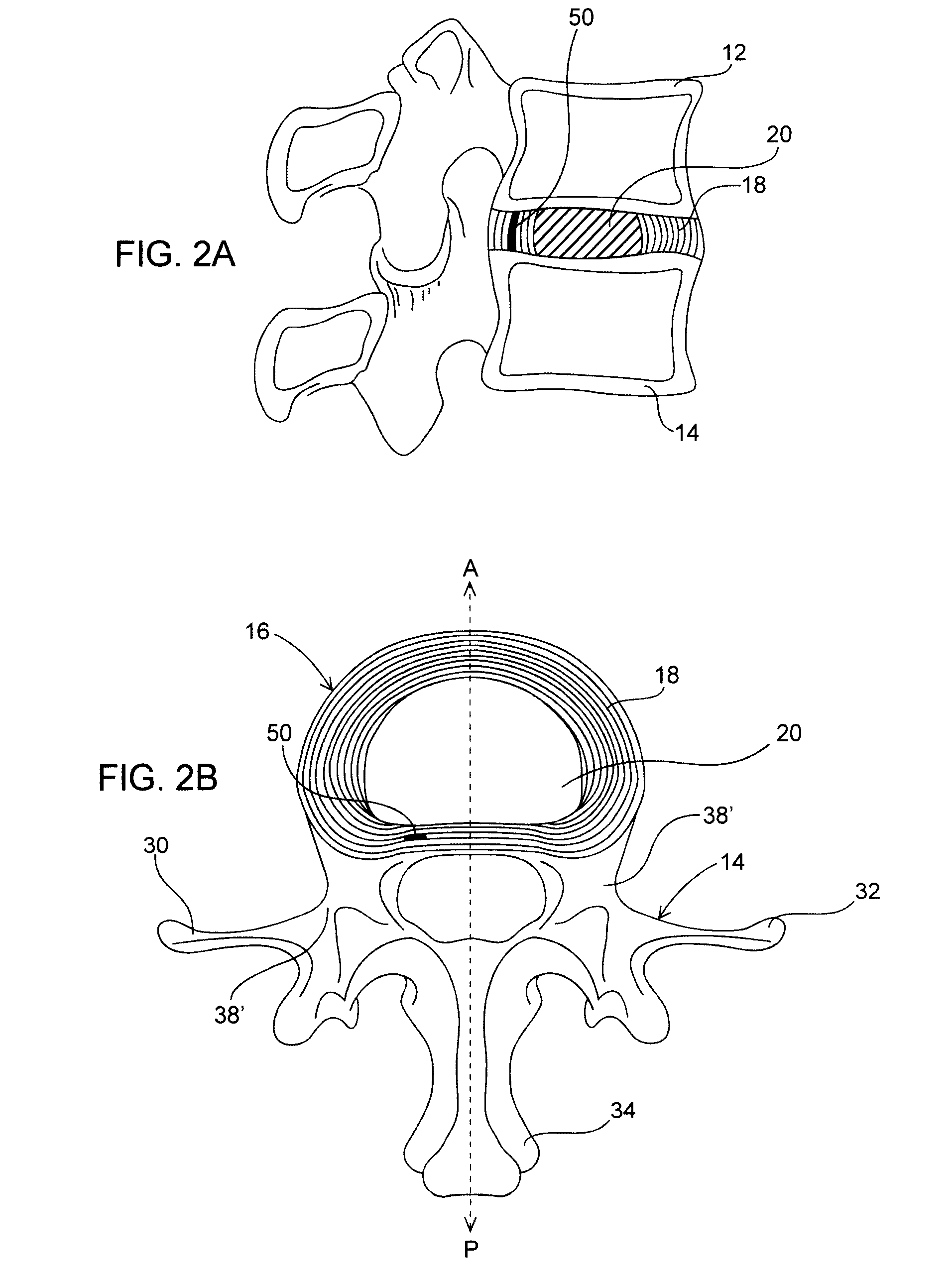
[0035] Unless defined otherwise, all technical and scientific terms used herein have the same meaning as commonly understood by one of ordinary skill in the art to which this invention belongs. For example, in this description and the following claims, the terms “anterior”, “posterior”, “superior” and “inferior” are defined by their standard usage in anatomy, i.e., anterior is a direction toward the front (ventral) side of the body or functional spine unit; posterior is a direction toward the back (dorsal) side of the body or functional spin unit; sup...


PUM

PropertyMeasurementUnit
heightaaaaaaaaaa
lengthaaaaaaaaaa
water contentaaaaaaaaaa

Abstract

Intervertebral disc implants are provided for augmenting the annulus of the disc in a manner to bear at least part of the axial and / or torsional load on the annulus so that rents, fissures and subsequent herniation of the disc are prevented or substantially delayed. An aspect of the subject devices is that they have an operative height dimension that is equal to or less than the disc height of a normally functioning, healthy disc. Methods and tools are also provided for the minimally invasive implantation of the device within an intervertebral disc.

Description

CROSS-REFERENCE TO RELATED APPLICATIONS [0001] This application is a continuation-in-part of U.S. patent application Ser. No. 11 / 139,731, filed on May 26, 2005, incorporated herein by reference.FIELD OF THE INVENTION [0002] The present invention is directed towards the augmentation of the annulus of intervertebral discs. BACKGROUND OF THE INVENTION [0003] The spinal column is formed from a number of bony vertebral bodies separated by intervertebral discs which primarily serve as a mechanical cushion between the vertebral bones, permitting controlled motions (flexion, extension, lateral bending and axial rotation) within vertebral segments. The normal, natural intervertebral disc is comprised of three component tissues: the nucleus pulposus (“nucleus”), the annulus fibrosis (“annulus”), and two opposing vertebral end plates. The two vertebral end plates are each composed of thin cartilage overlying a thin layer of hard, cortical bone which attaches to the spongy, richly vascular, can...

Claims


Application Information

Patent Timeline
Patent Type & Authority Applications(United States)
IPC IPC(8): A61F2/44
CPCA61F2/441A61F2310/00365A61F2/4611A61F2002/30075A61F2002/30092A61F2002/30131A61F2002/30136A61F2002/30181A61F2002/30235A61F2002/30289A61F2002/30327A61F2002/30579A61F2002/30583A61F2002/30599A61F2002/30677A61F2002/30841A61F2002/4435A61F2002/448A61F2002/4495A61F2002/4677A61F2210/0014A61F2210/0061A61F2210/0085A61F2230/0004A61F2230/0013A61F2230/006A61F2230/0069A61F2230/0091A61F2250/0039A61F2250/0063A61F2310/00017A61F2/442
Inventor SAAL, JEFFREY ALANSAAL, JOEL STUART
Owner SAAL JEFFREY ALAN
Why Eureka
Try Eureka